


www.airkinglimited.com
111597000 Rev. A 5-07
SECTION 5
Installing the Range Hood
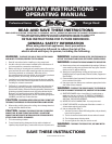
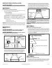
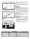
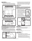
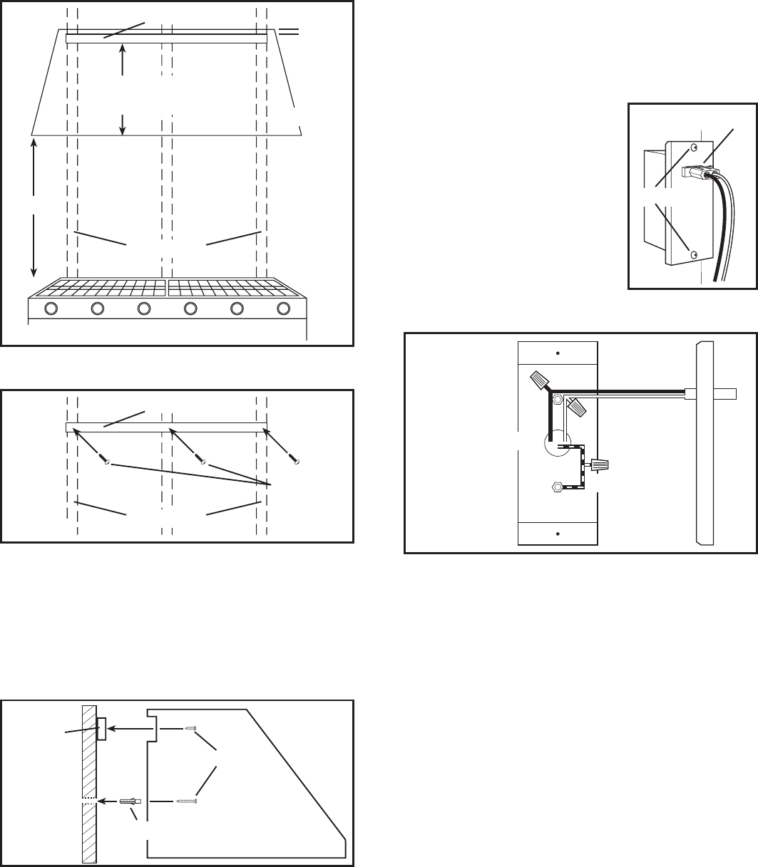
1. Measure and mark a level line on the wall above the cook top for the
included wood mounting strip. The height of the mounting strip will depend
on your specific installation and should be .75” below the top of the hood
canopy height
(Figure 5).
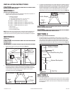
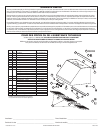
2. Secure the included wood strip in place using the provided 2" mounting
screws making sure the screws are fastening into the wall studs
(Figure 6).
CAUTION: DUE TO THE WEIGHT OF THE HOOD, ENSURE THE WOOD STRIP
IS FASTENED TO ALL AVAILABLE WALL STUDS (A MINIMUM OF 2 STUDS FOR 30"
HOODS, MORE AS THE WIDTH INCREASES) NOT INTO THE DRYWALL ALONE.
CAUTION: SUPPORT THE HOOD UNTIL IT IS FULLY INSTALLED ONTO
THE WOOD MOUNTING STRIP.
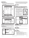
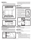
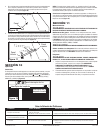
3. Rest the cavity on the back side of the hood on the wood strip and mark
drilling locations on the wall for wall anchors on the bottom rear of the
hood. Remove hood and install wall anchors
(Figure 7).
4. Rest the cavity on the back side of the hood on the wood strip and secure
hood to wood strip with the included 3/4" screws through the holes in the
back of the hood that line up with the wood strip (use 6 screws for 30" and
36" widths and 8 screws for larger widths) Secure the bottom of the hood
by installing the screws provided into the wall anchors.
(Figure 7).
SECTION 6
Wiring
CAUTION: ALL ELECTRICAL CONNECTIONS MUST BE MADE IN
ACCORDANCE WITH LOCAL CODES, ORDINANCES, OR NATIONAL ELECTRICAL
CODE. IF YOU ARE UNFAMILIAR WITH METHODS OF INSTALLING ELECTRICAL
WIRING, SECURE THE SERVICES OF A QUALIFIED ELECTRICIAN.
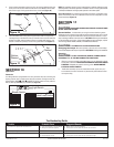
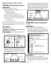
1. Remove the two wire compartment cover
screws to gain access into the wire
compartment (Figure 8). Connect the white
wire from the range hood to the white wire
from the supply, and the black wire from the
range hood to the black wire of the supply.
Connect the ground wire from the home
(green or bare) to the ground wire (green)
from the hood. Use approved methods for all
connections (Figure 9).
2. Replace the wire compartment cover and
tighten screws. Make sure all wiring is
securely contained within the wire
compartment. If the quick connect wire
connector was removed from the receptacle, replace. The connector will
only fit one way into the receptacle (Figure 8).
SECTION 7
Installing the Optional Soffits
1. Refer to the instructions included with the specific soffit(s) you have chosen
for installation.
SECTION 8
Installing the Blower
1. Refer to the instructions included with the specific blower you have chosen
for installation.
SECTION 9
Finishing the Installation
1. Install the proper lighting for your specific unit:
Halogen Lamps: Use PAR20, 50W maximum lamps (available
separately). Install by inserting lamp into socket and turning clockwise
until lamp is firmly seated. DO NOT over tighten.
Heat Lamps: Use PAR38, 175W infrared lamps only (available
separately). Install by inserting lamp into socket and turning clockwise
until lamp is firmly seated. DO NOT over tighten.
3 of 16
Figure 5
Cook Top
Wall Studs
24" - 36"
7.5" (10" high models)
15.5" (18" high models)
Hood
.75"
Wood Mounting Strip
Figure 6
Wall Studs
Wood Mounting Strip
Screws
Wood
Mounting
Strip
Figure 7
Hood
Screw
Figure 8
Screws
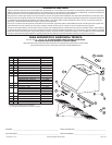
Figure 9
Supply from house
Hot (Black)
White
Ground
Wire Connector
Wall Anchor