


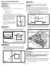
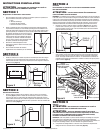
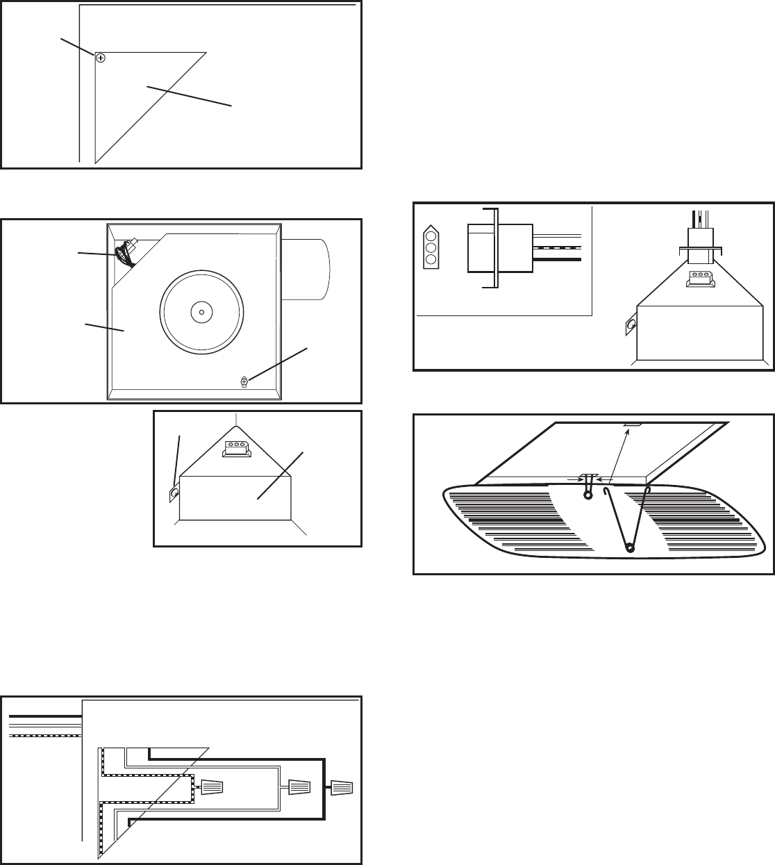
1b. Internal Wire Compartment: Remove the screw holding the venturi in place. Lift the
venturi up and at an angle to slide it out of the housing (Figure 7). Remove the wire
compartment cover screw and place the cover in a secure place (Figure 8).
NOTE: If the fan motor plug is
connected to the fan housing
receptacle, unplug so the blower
assembly can be completely removed.
2. Run wiring from an approved wall switch carrying the appropriate rating. One neutral
(white), one ground (green or bare copper), and one hot (black lead connected to the switch).
Secure the electrical wires to the housing with an approved electrical connector. Make sure
you leave enough wiring in the box to make the connection to the fan’s receptacle.
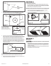
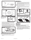
3. From where you have chosen to access the fan’s junction box, connect the White wire
from the house to the White wire from the fan’s receptacle. Connect the Black wire from
the wall switch to the Black wire from the fan’s receptacle. Connect the ground wire
from the house to the Green wire from the fan’s receptacle (Figure 9). Use approved
methods for all connections.
NOTE: The fan’s receptacle wires might need to be pulled outside compartment for connection.
Only pull the three loose wires outside of compartment. Additional wires will be present.
4. Carefully tuck wire back inside wire compartment and replace wire compartment cover
securing with the screw that was removed earlier.
www.airkinglimited.com
A210952009 Rev. N 6-15 3 of 8
SECTION 6
Completing the Installation
1. Use a sealant appropriate for contact with the building materials present and for the
temperature requirements of the installation to prevent air leakage from unconditioned
spaces is recommended. If gaps between unit housing and ceiling are great, additional
material (backing rod, ceiling material) may be required.
NOTE: This fan is rated for direct insulation contact (Type IC) and it is recommended that this fan
be completely covered by insulation in order to reduce heat loss or gain to unconditioned space.
2. If the fan’s blower assembly was removed during the wiring process, reinstall the
blower by reversing the directions in Section 5 (Wiring), Step 1b.
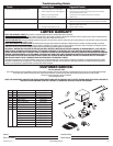
3. Plug the fan’s quick connect motor cord into the receptacle. This cord will only fit one
way into the receptacle (Figure 10).
4. Install the grill by squeezing the two ends of the springs together and installing them up
into the slots on the fan’s housing. Push the grill up into position (Figure 11).
5. Restore power and test your installation.
SECTION 7
Use and Care
CAUTION: MAKE SURE POWER IS SWITCHED OFF AT SERVICE PANEL BEFORE
SERVICING THE UNIT.
1. Cleaning the Grill: Remove grill and use a mild detergent, such as dishwashing liquid,
and dry with a soft cloth. NEVER USE ANY ABRASIVE PADS OR SCOURING POWDERS.
Completely dry grill before reinstalling. Refer to instructions in Section 6 Finishing the
Installation, to reinstall grill.
2. Cleaning the Fan Assembly: Wipe all parts with a dry cloth or gently vacuum the fan.
NEVER IMMERSE ELECTRICAL PARTS IN WATER.
Figure 6
Screw
Wire
Compartment
Cover
Figure 9
Supply from
house
Ground
White
Hot (Black)
Figure 8
Screw
Wire
Compartment
Cover
Plug
Figure 7
Venturi
Screw
Figure 11
Figure 10