


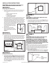
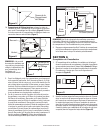
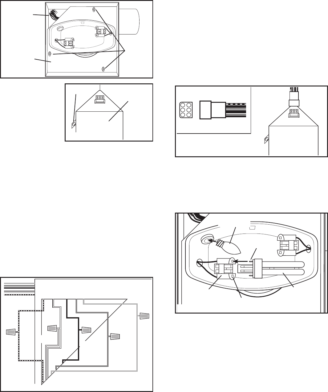
1b. Internal Wire Compartment: Remove the three screws holding
the blower assembly in place and lift assembly out of housing
(Figure 6). Remove the wire compartment cover screw and
place the cover in a secure place (Figure 7).
NOTE: If the fan motor plug
is connected to the fan
housing receptacle, unplug
so the blower assembly can
be completely removed.
2. Run wiring from an approved wall switch carrying the
appropriate rating. One neutral (white), one ground (green
or bare copper), and three hot (black, purple, yellow leads
connected to the switch, one for each function). Secure the
electrical wires to the housing with an approved electrical
connector. Make sure you leave enough wiring in the box to
make the connection to the fan’s receptacle.
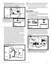
3. From where you have chosen to access the fan’s junction
box, connect the White wire from the house to the two White
wires from the fan. Connect one Hot (Black) wire from the
wall switch to the Black wire from the fan (this is the fan
control). Connect second Hot (Purple) wire from the wall
switch to the Purple wire from the fan (this is the main light
control). Connect the third Hot (Yellow) wire from the wall
switch to the Yellow wire from the fan (this is the night light
control). Connect the ground wire from the house to the
Green wire from the fan (Figure 8). Use approved methods
for all connections.
NOTE: The fan’s receptacle wires might need to be pulled outside
compartment for connection. Only pull the three loose wires
outside of compartment. Additional wires will be present.
4. Carefully tuck wires back inside wire compartment and
replace wire compartment cover securing with the screw
that was removed earlier.
SECTION 6
Completing the Installation
1. If the fan’s blower assembly was removed during the wiring
process, reinstall the blower by reversing the directions in
Step 1b
in Section 5
Wiring
.
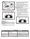
2. Plug the fan’s quick connect motor cord into the receptacle.
This cord will only fit one way into the receptacle (Figure 9).
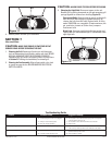
3. Install the two included 13 watt fluorescent bulbs into the
lamp holders by lining up the pins on the bulb base to the
socket of the lamp holder and pressing towards the lamp
holder until the bulb snaps into place and is firmly seated in
the lamp holder. Install a 4 watt maximum type C7 (candelabra
base) night light (not included) into the side lamp holder
(Figure 10).
4. Install the grill by squeezing the two ends of the springs
together and installing them up into the slots on the fan’s
housing. Push the grill up into position (Figure 11).
www.airkinglimited.com
210572080 Rev. A 8-05 3 of 12
Figure 8
Hot
(Black)
White
Supply from
house
Figure 9
Figure 6
Plug
Screws
Venturi
Screw
Wire
Compartment
Cover
Figure 7
Ground
Hot
(Purple)
Hot (Yellow)
Figure 10
Pin
Socket
Bulb
Lamp Holder
Night Light