


CAMPANA EXTRACTORA DECORATIVA
Estimado cliente:
Tenemos la certeza que la adquisición de nuestra campana
extractora va a satisfacer plenamente sus necesidades; para ello
le rogamos lea atentamente las instrucciones del manual con lo
cual obtendrá un resultado óptimo en la utilización de la misma.
IMPORTANTE
Para la obtención de nuestra garantía, será imprescindible pre-
sentar la factura de compra de la campana con el certificado de
garantía. Sin este requisito la garantía no tendrá validez.
INSTRUCCIONES PARA LA INSTALACIÓN,
MANUTENCIÓN Y USO
INDICACIONES GENERALES
• Antes de instalar y usar la campana, asegurar que la tensión
(V) y la frecuencia (Hz) indicadas en la placa de características
correspondan a la tensión y la frecuencia del lugar de instalación.
• La placa de características y los datos técnicos se encuen-
tran en el interior del producto.
Esta campana se suministra con un tubo telescópico, que per-
mite ajustarlo según la altura de la cocina.
CARACTERÍSTICAS TÉCNICAS
TENSIÓN y FRECUENCIA: 120 V 60 Hz
POTENCIA TOTAL: 570 W
MOTOR A TRES VELOCIDADES: 470 W
LÁMPARA: 2 x 50 W
INSTRUCCIONES DE INSTALACIÓN:
ADVERTENCIA – PARA REDUCIR EL RIESGO
DE INCENDIO, DESCARGA ELÉCTRICA O
DAÑO PARA LAS PERSONAS, OBSERVE LO
SIGUIENTE:
• El trabajo de instalación y el cableado eléctrico deben ser reali-
zados por personas cualificadas, de acuerdo con todos los códigos
y normas aplicables, incluyendo una construcción ignífuga.
• Es necesario air
e suficiente para la combustión correcta y la
extracción de los gases a través del canal de humos (chimenea)
del equipo de combustión para evitar el contratiro. Siga las ins-
trucciones del fabricante del equipo de calefacción y las normas
de seguridad como las publicadas por la Asociación nacional de
protección contra el fuego (NFPA) y la Sociedad americana de
ingenier
os de calefacción, refrigeración y aire acondicionado
(ASHRAE) y las Autoridades r
eguladoras locales.
• Cuando corte o taladre en la pared o en el techo, no dañe el
cableado eléctrico ni otras instalaciones de servicios ocultas.
• Los extractores entubados deben ventilarse siempre al exterior.
•
Utilice sólo conductos metálicos.
MONTAJE Y FIJACIÓN A LA PARED.
• Por favor, retirar las piezas de protección de espuma antes de
utilizar.
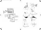
• Conectar la pieza plástica cónica de salida, suministrada con
la campana (diámetro 6") a un producto de evacuación conecta-
do directamente con el exterior. (Fig.1)
• Atornillar la caja de conexiones según Fig. 1 con los dos torni-
llos de 1/8" x 11/16" que se suministran en la bolsa de accesorios.
• Los accesorios necesarios para la instalación de la campana
se encuentran en el interior de la misma.
• Realizar los orificios en la pared usando una broca de 6 mm.
• En la bolsa de accesorios que se suministran con la campa-
na, encontrará los tacos y los tornillos necesarios para la fijación
de la misma.
• Este ventilador debe montarse a un mínimo de 22 pulgadas
sobre la fuente de calor.
CABLEADO
IMPORTANTE: Asegurase que todo el cableado cumple con las
leyes locales y que el aparato esté correctamente puesto a tierra.
• Extienda tres cables, dos de alimentación y uno de tierra,
desde la caja de empalmes de la campana hasta una caja de
empalmes próxima al lugar de instalación. Ver Fig. 1 Ref A
• Utilizando conectores para cables homologados, conecte los
conductores de alimentación a los conductores del ventilador:
negro con marrón y blanco con azul. Conecte el conductor de
toma de tierra (verde o desnudo) al conductor de masa (amari-
llo/verde) de la caja de distribución del ventilador.
MONTAJE DEL TUBO TELESCÓPICO EMBELLE-
CEDOR:
• Marcar en la pared la posición del soporte E (Fig. 2), según
cotas y especificaciones de la plantilla adjunta.
• Efectuar los agujeros en la pared, aplicar los tacos en los ori-
ficios y fijar el soporte E con los tornillos.
• Poner el tubo A con la parte telescópica B en su interior, ase-
gurándose que la pestaña D esté correctamente alojada en el
soporte E (Fig. 2).
• A continuación debe fijarse el soporte G en el extremo supe-
rior de la pared asegurándose de que la alineación respecto al
tubo telescópico es la correcta. Extender la parte móvil del tubo
B hasta alcanzar el soporte G y fijarlo con dicho soporte median
-
te los dos tornillos laterales. (Fig. 5).
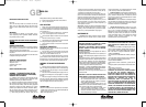
PANEL DE MANDOS
Este panel está situado en la parte fr
ontal de la campana y
compr
ende:
- 3 pulsadores para el control del motor (posición 1ª, 2ª y 3ª
velocidad) (ref. D).
E
ESPAÑOL
- Light switch (Ref. F).
TIMING: To operate the canopy timer, having selected the speed,
press the button for two seconds until the LED light blinks. The
timer will then work for 15 minutes.
At the end of this time, the motor will stop and the light will go
out. If it is still on, and you wish to cancel the timing, press the
timer button once and the motor will stop.
IMPORTANT: During an electrostatic discharge (ESD) it is possi-
ble that the device will stop working. By switching the device
OFF an ON the device will again work as intended. There is no
risk and no risk will appear.
MAINTENANCE
• Cleaning: Disconnect the power before cleaning or servi-
cing. Clean the external part with a mild, liquid detergent and
avoid the use of abrasive cleaning products.
• Changing the light: Before changing the light make sure
that the hood is not connected.
Remove the grease filter and replace the light with a light bulb no
more powerful than that specified in the Technical
Characteristics. Place the filter in position.
IMPORTANT: If the halogen lamps need replacing, they must be
replaced by lamps with an aluminium reflector, never dichroic
lamps, to avoid unnecessary overheating in the lamp holders.
• Cleaning the grease filter: Depending on use, and at least
once a month, the grease filters should be disassembled (Fig. 3)
and (fig. 4) and cleaned in a dishwasher or with hot soapy water.
If washed in a dishwasher they should be placed in an upright
position to prevent food remains from falling on them. After rin-
sing and drying, replace the filters by following the steps for
disassembly in reverse order.
IMPORTANT SAFETY INSTRUCTIONS:
WARNING: DISCONNECT THE RANGE HOOD FROM POWER
SUPPLY BEFORE SERVICING.
WARNING – TO REDUCE THE RISK OF FIRE, ELECTRIC SHOCK
OR INJURY TO PERSONS, OBSERVE THE FOLLOWING:
a) Do not use this fan with any solid state speed control device.
b) Use this unit only in the manner intended by the manufacturer. If
you have questions, contact the manufacturer.
c) Before servicing or cleaning unit, switch power off at service
panel and lock service panel to prevent power from being switched
on accidentally. When the service disconnecting means cannot be
locked, securely fasten a prominent warning device, such as a tag
to the service panel.
CAUTION: FOR GENERAL VENTILATING USE ONLY. DO NOT
USE TO EXHAUST HAZARDOUS OR EXPLOSIVE MATERIALS
AND VAPORS.
CAUTION: To reduce the risk of fire, use only metal duct work.
WARNING – TO REDUCE THE RISK OF A RANGE TOP GREASE
FIRE:
a) Never leave surface units unattended at high settings. Boilovers
cause smoking and greasy spillovers that may ignite. Heat oils
slowly on low or medium settings.
b) Always turn hood ON when cooking at high heat or when
flambeing food (i.e. Crepes Suzette, Cherries Jubilee,
Peppercorn Beef Flambé)
c) Clean ventilating fans frequently. Grease should not be allowed
to accumulate on fan or filter
.
d)
Use proper pan size. Always use cookware appropiate for the
size of the surface element.
WARNING – TO REDUCE THE RISK OF INJURY TO PERSONS
IN THE EVENT OF A RANGE TOP GREASE FIRE, OBSERVE
THE FOLLOWING:
a) SMOTHER FLAMES with a close-fitting lid, cookie sheet, or
metal tray, then turn off the burner. BE CAREFUL TO PREVENT
BURNS. If the flames do not go out immediately
, EV
ACUATE AND
CALL THE FIRE DEPARTMENT.
b) NEVER PICK UP A FLAMING PAN – you may be burned.
c) DO NOT USE WATER, including wet dishclothes or towels –
a violent steam explosion will result.
d) Use an extinguisher ONLY if:
1. You know you have a Class ABC extinguisher, and you
already know how to operate it.
2. The fire is small and contained in the area where it started.
3. The Fire Department is being called.
4. You can fight the fire with your back to an exit.
WARNING – SUFFICIENT AIR IS NEEDED FOR PROPER COM-
BUSTION AND EXHAUSTING OF GASES THROUGH THE FLUE
(CHIMNEY) OF FUEL BURNING EQUIPMENT TO PREVENT
BACK DRAFTING. FOLLOW THE HEATING EQUIPMENT
MANUFACTURER'S GUIDELINES AND SAFETY STANDARDS
SUCH AS THOSE PUBLISHED BY NATIONAL FIRE
PROTECTION ASSOCIATION (NFPA), AND THE AMERICAN
SOCIETY FOR HEATING, REFRIGERATION AND AIR
CONDITIONNING ENGINEERS (ASHRAE), AND LOCAL CODE
AHTHORITIES.
THE MANUFACTURER DECLINES ALL LIABILITY IN CASES
WHERE THE INSTRUCTIONS FOR THE APPROPRIA
TE
INST
ALLA
TION, MAINTENANCE AND USE OF THE
EXTRACTOR HOOD ARE NOT OBSER
VED.
60807600.14.09.2004 22/12/04 09:53 Página 10