


9
Converting 3-Wire to 4-Wire Power Cord
1. Remove rear wire cover.
2. Remove bottom cord clamp screw and retain for
further use.
3. Remove screw/hex nuts from terminal block and
retain for further use.
4. Remove all 3-wire or cable leads from the terminal
block and proceed to remove the power cord from the
range by pulling in a downward motion so the cord is
removed from strain relief.
5. To install the 4-wire cord, please follow step 3
through step 9 of
Installing 4-Wire Power Cord
section.
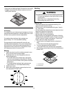
Level Range
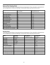
CAUTION
!
To avoid damaging oven door, do not lift or move range
by oven door handle. Glass can break.
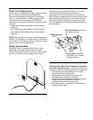
Carefully level range using legs provided. Range must be
level to cook and bake uniformly.
• Place a level on top oven rack or on range top when
leveling.
• Leveling legs must extended ¼ inch to engage anti-tip
bracket.
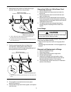
Removal and Replacement of Range
1. Disconnect power to range.
2. Slide range forward.
3. Unplug range cord and place range aside.
4. Remove anti-tip bracket.
5. Install anti-tip bracket into new location using
instructions provided with bracket or see
Anti-tip
Bracket Installation
section in this manual.
6. To reinstall range, follow instructions in
Installation
section of this manual.
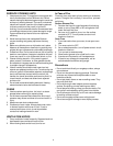
7. Attach power lead, red wire or black wire to right
terminal. Secure with hex nuts provided.
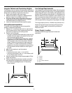
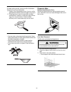
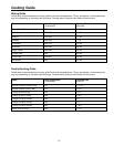
Wires from power cord
A
A
B
Wires from range
(Number of wires on each terminal can vary)
A—240 or 208 power lead terminal (Connect black or red
insulated wire and secure with brass nut.)
B—Neutral terminal (Connect insulated white insulated wire and
secure with brass nut.)
Attach Power Leads
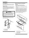
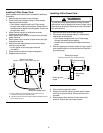
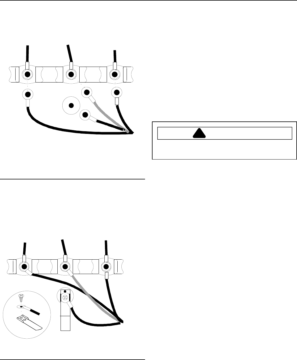
7. Position grounding strap down and away from
terminal block. Attach green or bare wire and
grounding strap to back of range using green ground
screw previously removed in step 3.
Wires from power cord
A
Wires from range
(Number of wires on each terminal can vary)
A—Ground screw (Connect green insulated wire and secure with
screw.)
Attach Green or Bare Wire and Grounding Strap
8. Firmly tighten all connections to ensure proper
electrical connection.
9. Place screw through strain relief, tighten, and replace
rear wire cover.