


Component Testing Information
I I WARNING
To avoid risk of electrical shock, personal injury, or death, diSconnect power to oven before servicing, unless
testing requires iL
I
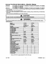
Illustration
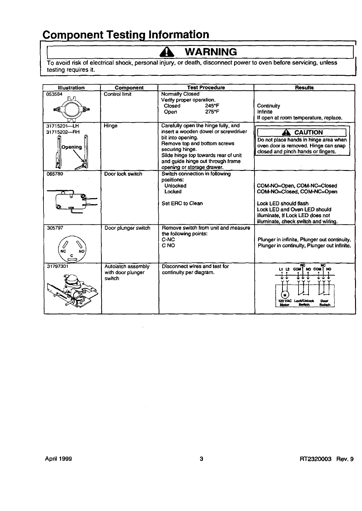
053584
31715201--LH
31715202--RH
065780
305797
31797301
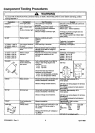
Component Test Procedure Results
Control limit Normally Closed
Verify properoperation.
Closed 245°F Continuity
Open 275°F Infinite
If open at roomtemperature, replace.
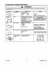
Hinge
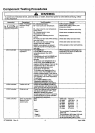
Door lock switch
Door plunger switch
Autotatchassembly
withdoor plunger
switch
Carefully openthe hinge fully,and
insert a wooden dowelor screwdriver
bitintoopening.
Remove top and bottomscrews
: securinghinge.
Slide hinge top towards rear ofunit
and guidehingeoutthrough frame
opening or storage drawer.
Switch connectioninfollowing
positions:
Unlooked
Looked
;et ERC to Clean
Remove switchfrom unitandmeasure
the following points:
C-NC
C NO
Disconnect wiresand testfor
continuityperdiagram
I 4_ CAUTION II
Do notplacehands inhinge area when
I
Ovendooris removed. Hinge can snap
closedand pinchhands or fingers.
COM-NO=Open, COM-NC=Closed
COM-NO=Clceed, COM-NC--Open
Lock LED shouldflash
LookLED andOven LED should
illuminate,If LockLED doesnot
illuminate,check switch and widng.
Plunger ininfinite,Plunger outcontinuity.
Plunger incontinuity,Plunger outinfinite.
NC NC
__, ,_
,:....a_H.__.....___.o_ _.. ;
April 1999 3 RT2320003 Rev 9