13
The Integrated HVAC System
WARNING: This unit is a quiet, efficient, low pres-
sure system. Special care and attention should be
given if connecting this unit to any other air han-
dler that may draw more air than this unit is de-
signed to accommodate.
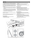
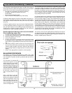
In installations where it is satisfactory to provide general
exhaust from the space, the air to be exhausted may be-
taken directly from the return air plenum to the HRV as it is
drawn back to the air handler. Fresh air supplied by the
HRV is then introduced directly into the return air plenum
Electrical Connections
Balancing
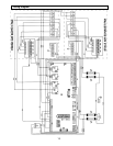
System is 208/240V, 1 phase, 60 Hz. This unit meets all
local codes and requirements.
It is STRONGLY recommended that an electrical discon-
nect be installed prior to the HRV, and that it is turned off
and locked out before servicing the unit.
The HRV 1500 SFD/SFDE have been programmed to provide
constant airflow on each airstream for external static pres-
sures of up to 1” w.g.
but at a location closer to the air handler. The air handler
would have a constant running blower to effectively distrib-
ute the fresh air and remove the stale air. Balancing damp-
ers would be located in both the HRV supply and exhaust
ducts between the return air plenum and the HRV.
In installations where it is necessary or desirable to have
an extended ducting system, it is recommended to have a
qualified designer/engineer size and design the ducting
system to ensure optimum removal and distribution of air is
achieved.
All electrical connections should be made by a qualified
electrician.
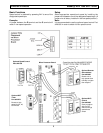
Two (2) knockouts are provided. One is to be used for line
voltage, and the other one for 24V control wires.
Within this range, each airflow can be adjusted as described
on page 5. After 1” w.g. of external static pressure, the unit
acts as a regular system and the following balancing pro-
cedure should be used.


