


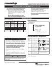
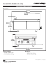

EGG STATION (ES-600 & ES-1200)
12
P/N 1010871 Rev. D 08/05
TROUBLESHOOTING (continued)
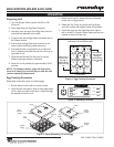
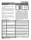
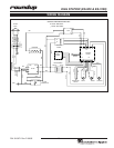
Control Board LEDs
The Control Board has three onboard LEDs (Figure
5) to determine the status of the unit and to assist in
troubleshooting.
Green (Diagnostic): The LED should be off in normal
operation however, if any of the 5 potential faults are
detected by the Control Board, this LED will repeatedly
blink either 1 through 5 times with a 2 second pause in
between (refer to the Green LED Blink Codes section
below).
Yellow (Audio): When lit, This LED indicates that the
Control Board is supplying approximately 10-15 VDC to
the audio signal. The audio signal should sound when
this LED is lit.
Red (Heat): When lit, this LED indicates that the
Control Board is calling for heat by supplying VDC to
terminals 3(+) and 4(-) of the Solid State Relay. When
off, it means that the grill platen is up to operating tem-
perature and satisfied
Green LED Blink Codes
Control Board
LED Activity
Unit State Condition
The Green LED
blinks on and off
1 time, pauses for
2 seconds, and
repeats
The EEPROM memory on the Control
Board is corrupted.
In this state, the unit turns off the control signal to the solid
state relay and disables all front buttons and lights. The unit
will not heat up. This continues until the defaults are reloaded
into memory. To reload the defaults, turn the unit off, press and
hold the Time 2 button, turn the unit back on, and release the
button.
The Green LED
blinks on and off
2 times, pauses
for 2 seconds, and
repeats.
The ambient temperature within the
control compartment has exceeded 155º
F (68º C). Verify that there is proper air
ventilation all around the unit and that it
is not near a significant heat source.
In this state, the unit turns off the control signal to the solid
state relay and disables all front buttons and lights. The unit
will not heat up. This continues until the ambient temperature
within the electrical compartment drops below 140º F (60º C)
and the unit is turned off and back on.
The Green LED
blinks on and off
3 times, pauses
for 2 seconds, and
repeats.
Open or disconnected Thermocouple. In this state, the unit turns off the control signal to the Solid
State Relay and disables all front buttons and lights. The unit
will not heat up. This continues until the Thermocouple is
reconnected or replaced, and the unit is turned off and back
on.
The Green LED
blinks on and off
4 times, pauses
for 2 seconds, and
repeats.
The supply voltage to the unit is below
160 VAC or above 265 VAC.
In this state, the unit turns off the control signal to the Solid
State Relay and disables all front buttons and front lights. The
unit will not heat up. This continues until the supply voltage is
within the proper limits and the unit is turned off and back on.
The Green LED
blinks on and off
4 times, pauses
for 2 seconds, and
repeats.
The 50/60 Hz signal has been lost due
to a loose, disconnected, or an open
wire harness/wiring on the AC Isolator
Board, or from the AC Isolator Board to
the Control Board.
In this state, the unit turns off the control signal to the Solid
State Relay and disables all front buttons and lights. The unit
will not heat up. This continues until the 50/60 Hz signal is
reapplied and the unit is turned off and back on.
NOTE: During heat mode, this Red LED is very dim,
so it may be difficult to verify if the Control Board
is, or is not, calling for heat. It is recommended
that you observe the small round green LED on the
Solid State Relay (Figure 6)for mode and diagnostic
purposes. When the green LED on the Solid State
Relay is on, it means that the Control Board is call-
ing for heat. When off, it means that the Control
Board is NOT calling for heat. Typically, the VDC at
the Solid State Relay will be less than 1.0 VDC when
measured, but may vary because of different quality
VOMs. Therefore, it is recommended that you DO
NOT attempt to measure the VDC at the Solid State
Relay for diagnostic purposes.
YELL
HEAT
RED
GRN
BUZZ
STATUS
CR4CR6 CR5
Green
Yellow
Red
Figure 5. Control Board
LEDs
Figure 6. Solid State
Relay
R
PRODUCTSERVICE
TUV
.
gapruit
Bauart
Crouzet
GN
841
37220
4/A2-
3-3
2VDC
+3/A1
1/L1
2/T1
50AMP24-280VAC
Solid State
Relay
LED