


4
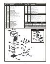
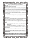
INSTALLATION
Installation:
1. Follow applicable General Installation Instructions on page 2.
2. Make applicable Cut-Out per above table. CONNECTION NOTE: Unit is designed for installation in
stainless steel tops. Optional wood mounting kit available.
3. Apply putty tape (Provided) to the underside perimeter of the well rim outer edge.
4. Apply a 1/4" (.6 cm) bead of silicone sealant adjacent to the putty tape on the well flange.
5. Drop well into opening from the top and push down until entire parameter of rim is flush with the
counter surface.
6. From below the counter surface insert an 8" to 10" (20 cm to 25 cm) flat tip screwdriver into the
locking ring tab slots and twist in a clockwise motion to lock well in place.
7. Trim excess putty and sealant from around well rim.
8. Mount control to front panel using hardware. Maintain 4" clearance between well and front panel.
Connect power. Check power. Check nameplate for proper voltage. NOTE: Electrically connect
unit in compliance with local and NEC codes.
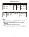
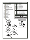
Full Size
(HFW-1)
2/3 Size
(HFW-23)
1/2 Size
(HFW-12)
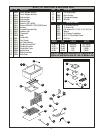
2
Description
HFW-1D
HFW-23D
HFW-12D
Models
w/Drains
1 11/16” x 1 11/16”
(4.3 x 4.3) from
back right corner
Drain
Location
½ NPT
Stainless
1 1/2” (3.8)
long
Drain
Couplings
72” (182.8)
Capillary
Effective
Length
62” (157.5)
Thermostat
56431
56460
56413
Wood Mt
Kit No’s
23 7/8” x 15 7/8”
(60.6 x 40.3)
16 5/8” x 15 7/8”
(42.2 x 40.3)
Wood Mt
Kit Cut-Out
13 5/8” x 15 7/8”
(34.6 x 40.3)
OPTION SPECIFICATIONS
ELECTRICAL SPECIFICATIONS
Description
Rating at 120VAC, 1PH Rating at 208VAC, 1PH Rating at 208/240VAC, 1PH
HFW-1 1500 Watts, 12.5 Amps 1660 Watts, 7.7 Amps 1200/1600 Watts, 5.7/6.7 Amps
HFW-23 800 Watts, 6.7 Amps
HFW-12 800 Watts, 6.7 Amps 500/660 Watts, 2.4/2.8 Amps