


7AQ4 Manual
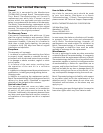
2.5 Vent piping
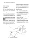
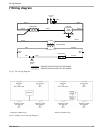
1. Install 5" to 4" reducer pipe on top of the water
heater and then connect a 4" 90º elbow to begin
the horizontal run. Use 4” vent pipe to connect
from this elbow to the power vent motor inlet,
avoiding elbows when possible. The maximum
vent length from the water heater to the point of
termination is 25 feet with one elbow. (Fig. 5) If
using more than one 90° elbow, subtract 5 feet
off the maximum vent length for each additional
elbow used. A maximum of three elbows is
allowed. The minimum straight vent length is 2
ft.
2. Support the vent pipe in accordance with vent
pipe manufacturer’s instructions. Vent pipe is not
supplied in the power vent kit, with the exception
of the 5" to 4" reducer in the AQ4 kit. Observe
the clearances associated with the class of vent
pipe used. 4" single wall galvanized, 4" stainless
steel or 4" B-vent pipe is required.
2.6 Linear safety spillage switch
The linear safety spillage switch provides a means for
safety shut down of the water heater in the event of
ue blockage or power vent failure. If hot ue gases
spill from the draft hood diverter, the draft spillage
sensing switch will open the pilot safety circuit and
shut off all gas to the water heater. The switch is
normally closed and opens at temperatures greater
than 185º F. It has a manual reset button.
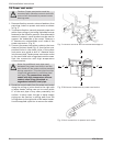
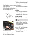
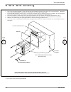
Mounting the linear safety spillage switch
1. Attach the spillage switch to the top left of the
heater’s draft diverter using the existing hole and
the included mounting screw. (Fig. 6)
2. Lay copper capillary sensing tube across top of
the draft diverter. Allow excess tube to hang down
right side of heater. Do not cut or crimp capillary
tube.
3. Route the two wires from the spillage switch
down the left side of heater to the ECO keeping
the cables out of contact with hot surfaces. (Fig.
6)
Connecting linear safety spillage switch to pilot
safety circuit
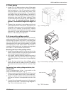
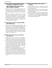
The ECO/temperature limiter is mounted on the
lower left outlet water pipe. (Fig. 7)
1. Remove one wire lead connected to ECO terminal
(it does not matter which one is disconnected).
2. Attach ¼" quick connect terminal end of linear
spill switch cable to now exposed terminal of the
ECO.
3. Connect the male spade connector to the removed
lead wire from step 1. See the wiring diagram in
Fig. 13 to conrm proper set up.
Fig. 5 Venting setup
AQ4 Installation instructions
Fig. 6 Linear safety spillage switch mounting
Fig. 7 ECO location
ECO terminals