


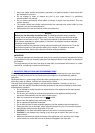
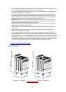
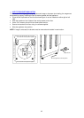
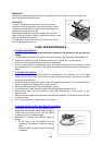

¾ ANTI-TIP BRACKET INSALLATION
To reduce the risk of tipping the range by abnormal usa r improper door loading, the range must
stalling the anti-tip device packed with the appliance.
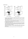
cket on the floor as shown figure. It can be installed on either right or left
• Mark the locations of the 2 holes of the ant-tip bracket on the floor.
• Use a 5/16” masonry the drill bit and insert plastic anchor.
• Secure the bracket to the floor using the screws supplied.
• Slide the appliance into position.
NOTE: If range is relocated, the bracket must be removed and installed in new location.
ge o
be secured by properly in
Place the anti-tip bra•
side.
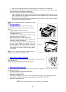
1.30"
5.69"
1.18"
The contour line of back panel of appliance
Install the anti-tip bracket either right or left side.
Anti-tip
Bracket
The contour line of left panel of appliance
ontou of right panel of appliance
The contour line of front panel of appliance
The c r line
Move the appliance to the final position.
-tip BracketAnti
17