


Baldor Electric Company, P. O. Box 2400, Ft. Smith, AR 72902-2400, (479) 646-4711, Fax (479) 648-5792
6HULHV0LFUR,QYHUWHU6XSSOHPHQWDO,QIRUPDWLRQ
Part No. MN781-SUP
(A42126) - Rev. D2 - 1/29/2004 - Z2746D02 Page 2 of 2
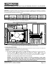
Figure 2A
Control Set for 230 Volts AC Line Input
(Factory Setting)
(Jumper J1 in the "230V" Position)
Figure 2B
Control Set for 115 Volts AC Line Input
(Jumper J1 in the "115V" Position)
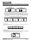
1-2. Motor Frequency Selection (Jumpers J1 and J2, on the Lower PC Board): The controls are factory set to
operate 60 Hz motors (Jumper J1 factory set to the "60Hz" position and Jumper J2 factory set to the "X1" position).
To operate 50 Hz motors, set Jumper J1 to the "50Hz" position. (Be sure that Jumper J2 is set to the "X1" position.)
To operate 120 Hz motors, be sure that Jumper J1 is set to the "60Hz" position and set Jumper J2 to the "X2"
position. To operate 100 Hz motors, set Jumper J1 to the "50Hz" position and set Jumper J2 to the "X2" position.
See Figure 3 below.
Figure 3 - Motor Frequency Selection (Jumpers J1 and J2)
60 Hz Motor Operation
(Factory Setting) 50 Hz Motor Operation 120 Hz Motor Operation 100 Hz Motor Operation
1-3. Other Jumpers: For other jumper settings, see the manual.
$&/LQH)XVLQJ
Install a fuse or circuit breaker in the AC line. Fuse each conductor that is not at ground potential. See Section VI, on
page 19 of the manual. See Table 2 below.
Table 2 - Fuse Selection Chart
AC Line Voltage
(Volts AC)
Maximum AC Line Current
(Amps AC)
AC Line Fuse
(Amps)
115 22.0 30
230 14.0 20
7ULPSRW$GMXVWPHQWV
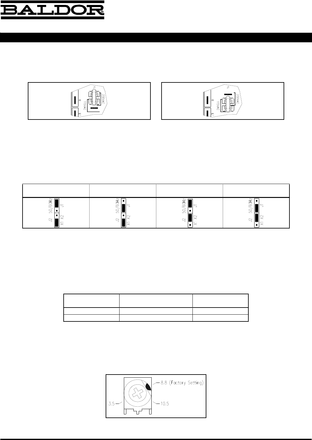
All trimpots have been factory set for most applications, as described in Section IX, on pages 22 - 27 of the manual. The
figure below shows the CL trimpot setting, which will be added to Section IX-E, on page 24 of the manual. See Mechanical
Specifications and Control Layout, above, for the location of trimpots. See Figure 4 below.
Figure 4 - CL Settings