


Manual 2100-533A
Page 4 of 12
The ERV units are wired from the factory on medium
intake and low exhaust speeds. The ERV is equipped
with independently controlled 3-speed motor to provide
the capability of adjusting the ventilation rates to the
requirements of the specific application and to be able to
provide positive pressure in the structure. This is
accomplished by setting the intake blower on a higher
speed than the exhaust blower.
RECOMMENDED CONTROL
SEQUENCES
Several possible control scenarios are listed below:
1. Use a programmable electronic thermostat with
auxiliary terminal to control the ERV based on daily
programmed occupancy periods. Bard markets and
recommends Bard Part No. 8403-060 programmable
electronic thermostat for heat pump applications.
2. Use a motion sensor in conjunction with a
mechanical thermostat to determine occupancy in
the classroom. Bard markets the CS2000A for this
use.
3. Use a DDC control system to control the ERV based
on a room occupancy schedule.
4. Tie the operation of the ERV into the light switch.
The lights in a room are usually on only when
occupied.
5. Use a manual timer that the occupants turn to
energize the ERV for a specific number of hours.
6. Use a programmable mechanical timer to energize
the ERV and indoor blower during occupied periods
of the day.
7. Use Bard Part No. 8403-056 CO
2
controller for “on-
demand” ventilation.
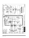
CONTROL WIRING
The QWSERV comes wired in the low voltage control
circuit from the factory.
With the “X” Remote Thermostat Option, it is default
wired into the “A” terminal, which drives the vent to
operate only during occupied periods when using a Bard
8403-060 thermostat or Bard CS2000 controller. If you
prefer for the QWSERV to operate anytime the blower
is operational, you will need to install a jumper wire
from “G” to “A”. If you prefer to use Bard 8403-056
CO
2
controller to make the ventilation “on-demand”,
there is a connection adjacent to the thermostat
connections in the unit upper right-hand corner, and is
marked to match CO
2
controller connections.
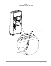
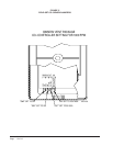
Furthermore, disconnect and tape off the wire as shown
in Figure 4 and you will need to field set the CO
2
sensor
jumpers per Figure 5.
With the “D” Door Mounted Thermostat Option, the
thermostat is already connected and programmed to
operate the QWSERV only during occupied periods.
With the “H” Door Mounted Thermostat and CO
2
controller, the unit is ready to go with “on-demand”
ventilation as controlled by the CO
2
controller.
VENTILATION AIRFLOW
The ERV is equipped with a 3-speed motor to provide
the capability of adjusting the ventilation rates to the
requirements of the specific application by simply
changing motor speeds.
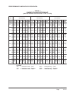
TABLE 1
VENTILATION AIR (CFM)
deepShgiH
)kcalB(
deepSmuideM
)eulB(
deepSwoL
)deR(
MFC
054573003
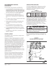
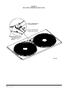
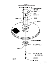
WARNING
Open disconnect to shut all power OFF before
doing this. Failure to do so could result in injury
or death due to electrical shock.
FIGURE 1
BLOWER SPEED ADJUSTMENT
Moving the speed taps located in the control panel can
change the blower speed of the intake and exhaust. See
Figure 1.