


Manual 2100-416
Page 18
LOW VOLTAGE CONNECTIONS
These units use a grounded 24 volt AC low voltage
circuit.
The “R” terminal is the hot terminal and the “C”
terminal is grounded.
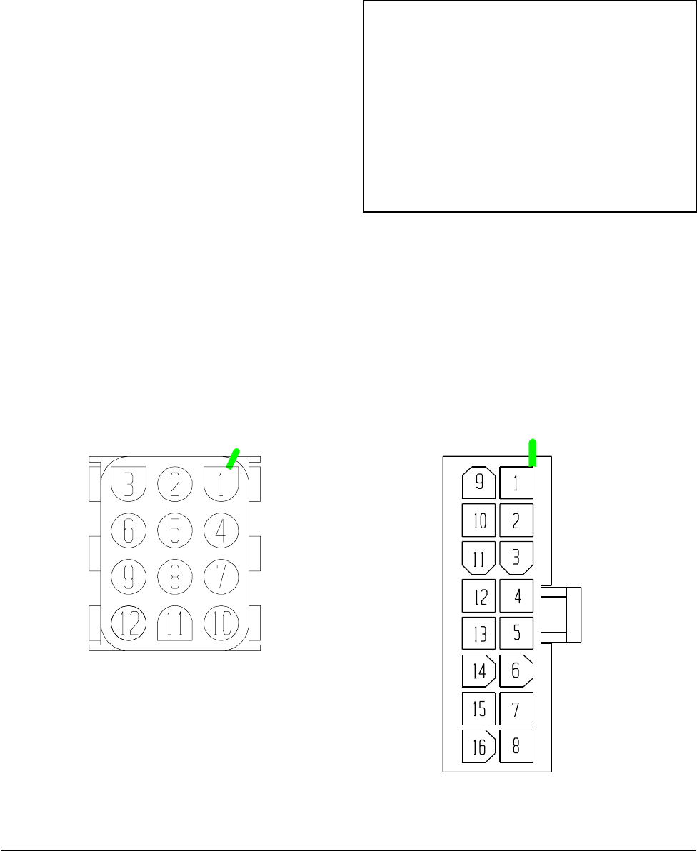
“G” terminal or pins 6 and 1 of P2 are the fan inputs.
Both must be energized for proper fan operation. This
is done automatically in the factory installed climate
control options. If the climate control option is
abandoned and connections are made directly to P2
both pins 6 and 1 of P2 must be energized for proper
operation.
“Y” terminal or pin 7 of P2 is the first stage cooling
input.
“B” terminal or pin 8 of P2 is the first stage heating
input.
“R” terminal or pin 10 of P2 is 24 VAC hot.
“C” terminal or pin 11 of P2 is 24 VAC grounded.
“L” terminal or pin 12 of P2 is the second stage
cooling input.
“W2” terminal or pin 9 of P2 is second stage heating
output.
“O1” terminal of pin 5 of P2 is the ventilation input.
This terminal energizes any factory installed ventilation
option.
Fan Only Energize G
1st Cooling Mode Energize Y, G
2nd Cooling Mode Energize Y, L, G
1st Stage Heating Energize G, B
2nd Stage Heating Energize G, B, W2
Ventilation Energize G, O1
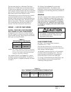
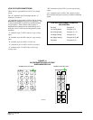
LOW VOLTAGE CONNECTIONS FOR
DDC CONTROL
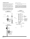
FIGURE 15
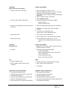
BLOWER MOTOR LOW VOLTAGE
WIRE HARNESS PLUG
MIS-1285
VIEWED FROM PIN END
VIEWED FROM PIN END