


12
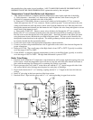
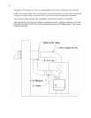
With the burner operating, use a draft gauge to adjust the regulator to the proper setting (see instructions
enclosed with draft gauge to adjust the regulator to the proper setting). When the burner air supply and draft
are properly adjusted, the draft in the flue should be a negative .02" W.C. to negative .04” W.C.
Two or more oil burning appliances each equipped with a safety control may be permitted to be connected
to one common chimney if sufficient draft is available for the safe simultaneous removal of all products of
combustion.
If two or more openings are provided into one chimney, they shall be at different levels on the same story of
the building, with the smaller appliance entering at the highest possible level consistent with clearances to
combustible materials.
Two or more connectors shall not be joined together unless the common connector, manifold and chimney
are properly sized. Adequate draft must be available to safely remove all products of combustion
simultaneously without leakage, or back flow.
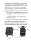
Direct Venting
Failure to follow all instructions can result in flue gas spillage and carbon monoxide
emissions, causing severe personal injury or death. All installations must meet the requirements of
NFPA31. Use only the ETL listed venting system components supplied with the packaged boiler. All vent
connections must be securely fastened and sealed with high temperature sealant.
WARNING
External vent surfaces are hot. Surface discoloration of the building may occur due to improper
burner or boiler adjustment. We will not accept any liability for such discoloration.
Caution
Follow all instructions which are included with your specific direct vent kit.
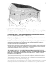
1. Choose the vent location. The preferred location of venting system is on the opposite wall of the known
prevailing winds.
2. The exit terminal of the system must conform to the following guidelines. See figure on following
page.
a. The vent terminal shall not be less than 3 feet above any forced air inlet to the house.
b. The vent terminal shall not be less than 4 feet below, 4 feet horizontally, or 1 foot above any
door window or gravity inlet into the building.
c. The vent terminal shall be installed at least 1 foot above ground. The vent must be
maintained to keep the location 1 foot above any solid surface including snow, ice and
landscape materials. The vent shall not be installed in a window well or any other
fabricated depression.
d. The vent terminal shall not be less than 2 feet from an adjacent building.
e. The vent terminal shall not be less than 7 feet above grade when located adjacent to public
walkways.
f. The vent terminal shall not be located so that flue gasses are directed to jeopardize people or
overheat combustible structures, materials or enter buildings.
g. All joints in the vent system are to be sealed with Permatex high temperature sealer or
equivalent to prevent the leakage of products of combustion into the building