


9 EURORACK UB1202/UB1002/UB802/UB502 User Manual
+48 V
The red +48 V LED lights up when phantom power is on. The PHANTOM switch
activates the phantom power supply on the XLR connectors of all mono channels.
◊ Please do not connect microphones to the mixer (or the
stagebox/wallbox) as long as the phantom power supply is
switched on. Connect the micro-phones before you switch on the
power supply. In addition, the monitor/PA loudspeakers should be
muted before you activate the phantom power supply. After switching
on, wait approx. one minute in order to allow system stabilization.
POWER
The blue POWER LED indicates that the console is powered on.
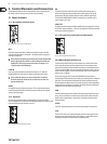
Level indicator
The high-precision 4-segment display accurately displays the relevant
signallevel.
LEVEL SETTING: To correctly set the gains of the channels, rst set the LEVEL
controls of the input channels to their center positions (0 dB). Then use the GAIN
controls to increase the input amplication until signal peaks show 0 dB on the
level meter.
When recording to digital recorders, the recorder’s peak meter should not
go into overload. While analog recorders can be overloaded to some extent,
creatingonlya certain amount of distortion (which is common and often
desirable), digitalrecorders distort quickly when overloaded. In addition,
digitaldistortion is not only undesirable, but also renders your recording
completely useless.
◊ The peak meters of your EURORACK display the level virtually
independent of frequency. A recording level of 0 dB is recommended
for all signal types.
3. Installation
3.1 Mains connection
AC POWER IN
Connect the power supply to the 3-pin mains connector on the rear of the
console. Use the AC adapter supplied to connect the console to the mains.
Theadapter complies with all applicable safety standards.
◊ Please use only the power supply unit provided with the console.
◊ Never connect the EURORACK to the power supply unit while the latter
is connected to the mains! First connect the console to the power
supply unit, then connect the power supply unit to the mains.
◊ Please note that both the power supply unit and the mixing console
heat up considerably during operation. This is completely normal.
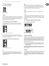
3.2 Audio connections
You will need a large number of cables for dierent applications. The illustrations
below show how the connectors should be wired. Be sure to use only
high-gradecables.
Please use commercial RCA cables to connect the 2-track inputs and outputs.
You can, of course, also connect unbalanced devices to the balanced
inputs/outputs. To do this, use either mono plugs or stereo plugs with the ring
and sleeve bridged (pins 1 and 3 in the case of XLR connectors).
◊ Caution! Never use unbalanced XLR connectors (PIN 1 and 3 connected)
on the MIC input connectors when using the phantom power supply.
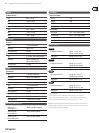
output
For unbalanced use, pin 1 and pin 3
have to be bridged
1 = ground/shield
2 = hot (+ve)
3 = cold (-ve)
input
12
3
1
2
3
Balanced use with XLR connectors
Fig. 3.1: XLR connections
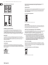
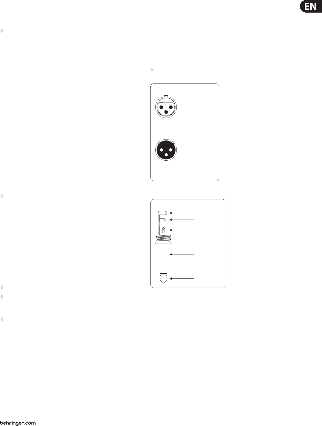
strain relief clamp
sleeve
tip
sleeve
(ground/shield)
Unbalanced ¼" TS connector
tip
(signal)
Fig. 3.2: ¼" mono plug