


3
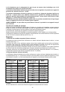
The minimum gas supply pressure for checking the regulator setting shall be at least 1“ w.c. (249 Pa)
above the inlet specified manifold pressure to the appliance (this operating pressure is 4” w.c.
(1.00 kPa) for Natural Gas and 11” w.c. (2.75 kPa) for LP Gas).
ATTENTION: A manual valve shall be installed in an accessible location in the gas line external to the
appliance for the purpose of turning on or shutting off gas to the appliance
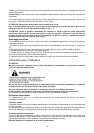
WARNING: Do not use aerosol sprays in the vicinity of this appliance while it is in operation
Inserting the hotplate
After having removed the various loose parts from the internal and external packing, make sure that the
hotplate in not damaged and is suitable for the specific gas usage. The gas type label is on the underside of
the hotplate base.
In case of doubt, do not use the appliance and contact skilled personnel.
Keep all the packing parts (polystyrene foam, cardboard, staples, etc.) away from children.
Consider the critical dimensions of the appliance, before making an opening in the top surface of the bench
top. (relative measurements as per Fig 1- 2).
Requirements
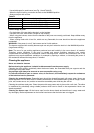
1. Overhead clearances (Minimum values)
The minimum overhead clearances shall be in accordance with the minimum values indicated in the table
n.1 and are shown and in the fig. 1- 2
Range hoods and exhaust fans shall be installed in accordance with the manufacturer’s instructions.
However, in no case shall the clearance between the top of the highest burner of the cooking appliance and
the range hood be less than 30”( 762mm). See Fig. 1- 2.
Any other downward facing combustible surface less than 600mm above the top of the highest burner shall
be protected for the full width and depth of the cooking surface area.
However, in no case shall this clearance to any surface be less than 17
3/4”(450mm.)
Maximum depth for the overheads cabinet is 13” (330mm)
2. Side clearances (Minimum values)
The different side clearances shall be in accordance with the minimum values indicated in the table n.1 and
are shawn and in the fig. 1- 2
The cooking surface area is defined as that part of the appliance where cooking normally takes place and
does not include those parts of the appliance containing control knobs.
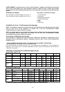
Table n.1
Hobs models
B3W0…
B3Y0…
Hobs models
B3W0…
B3Y0…
Min. Clearances inches (mm) Min. Clearances inches (mm)
L1
20
1/2” (520)
L10
35 10/16” (905)
L2
1
9/16“ (40)
L11
36“ (915)
L3
1
9/16“ (40)
W
36 1/2“ (925)
L4
18” (457)
D
21
1/4“ (540)
L5
24” (610)
B1 (*)
1
9/16“ (40)
L6
13” (330)
B2 (*)
6“ (152)
L7
36
1/2“ (925)
B3 (*)
1 3/16” (30)
L8
3/4“ (20)
B4 (*)
6“ (152)
L9
6
3/8” (162)
(*) Note:
-B1 is the min. clearance between the front edge of the appliance and the front edge of the cabinet.
-B2 and B4 are the min. clearance between the left/right side edge of the appliance and the side wall (if
present).
-B3 is the min. clearance between the back edge of the appliance and the back wall.