10
INSTALLINGTHEANTI‐TIPSTABILlTY
DEVICE
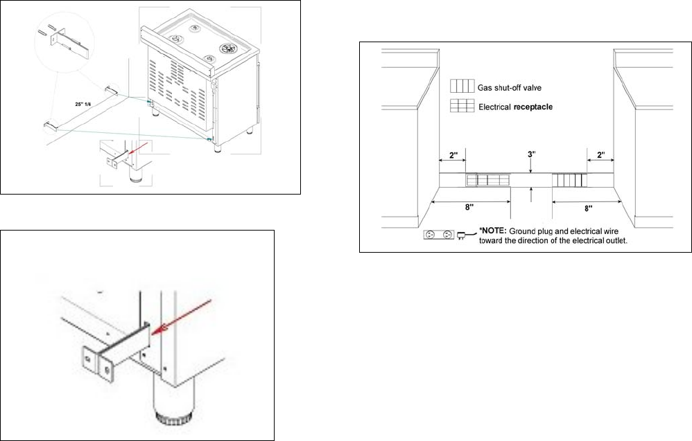
Theanti‐tipbracketshippedwiththerangemust
beproperlysecuredtotherearwallasshownin
thepircturebelow.
Theheightofthebracketfromthefloormustbe
determinedaftertherangelegshavebeen
adjustedtothedesiredheightandafterthe
rangehasbeenleveled.
Measurethedistancefromthefloortothe
bottomoftheanti‐tipbracketreceptacleonthe
backoftheappliance.
Positionthetwoanti‐tipbracketsonthewallat
thedesiredheightplus1/8"(0.32cm).The
bracketsmustbeplacedat2”5/16(6,0cm)from
theside
oftherange.Thedistancebetweenthe
twobracketis25”1/4(64cm).
Securethebracketstothewallwithappropriate
hardware.
Slidetherangeagainstthewalluntilthebrackets
arefullyinsertedintotheirreceptaclesonthe
backoftherange.
INSTALLATIONREQUIREMENTS
ELECTRICAL
Aproperly‐groundedhorizontally‐mounted
electricalreceptacleshouldbeinstallednohigher
than3"(7.6cm)abovethefloor,nolessthan2”
(5cm)andnomorethan8”(20,3cm)fromthe
rightside(facingproduct).
Checkalllocalcoderequirements.
GAS
Anagency‐approved,properly‐sized
manualshut‐
offvalveshouldbeinstallednohigherthan3"
(7.6cm)abovethefloorandnolessthan2”(5
cm)andnomorethan8” (20.3cm)fromtheleft
side(facingproduct).
Toconnectgasbetweenshut‐offvalveand
regulator,useagency‐approved,properlysized
flexible
orrigidpipe.Checkalllocalcode
requirements.


