7
To replace the power cable, lift the terminal board’s cover and replace the cable. To access the terminal board in cookers
with a 3x2.5mm² cable, the back panel on the rear of the appliance must be removed.
USE AND MAINTENANCE MANUAL
WARNING: This appliance is not intended for use by persons (including children) with reduced physical,
sensory or mental capabilities, or lack of experience and knowledge, unless they have been given supervision
or instruction concerning use of the appliance by a person responsible for their safety.
WARNING: Children should be supervised to ensure that they do not play with the appliance.
DO NOT USE OR STORE FLAMMABLE MATERIALS IN THE APPLIANCE STORAGE DRAWER OR NEAR THIS
APPLIANCE.
DO NOT SPRAY AEROSOLS IN THE VICINITY OF THIS APPLIANCE WHILE IT IS IN OPERATION.
DO NOT STORE OR USE FLAMMABLE LIQUIDS OR ITEMS IN THE VICINITY OF THIS APPLIANCE.
WHERE THIS APPLIANCE IS INSTALLED IN MARINE CRAFT OR IN CARAVANS, IT SHALL NOT
BE USED AS A
SPACE HEATER.
WARNING: SERVICING SHOULD BE CARRIED OUT ONLY BY AUTHORISED PERSONNEL.
DO NOT MODIFY THIS APPLIANCE.
Table 4 GAS BURNER DIMENSION (fig.21-22)
Burne
r
Dimension (mm)
Auxiliary Ø 50
Semi-rapid Ø 70
Rapid Ø 95
Dual Ø 140
CONTROL PANEL DESCRIPTION
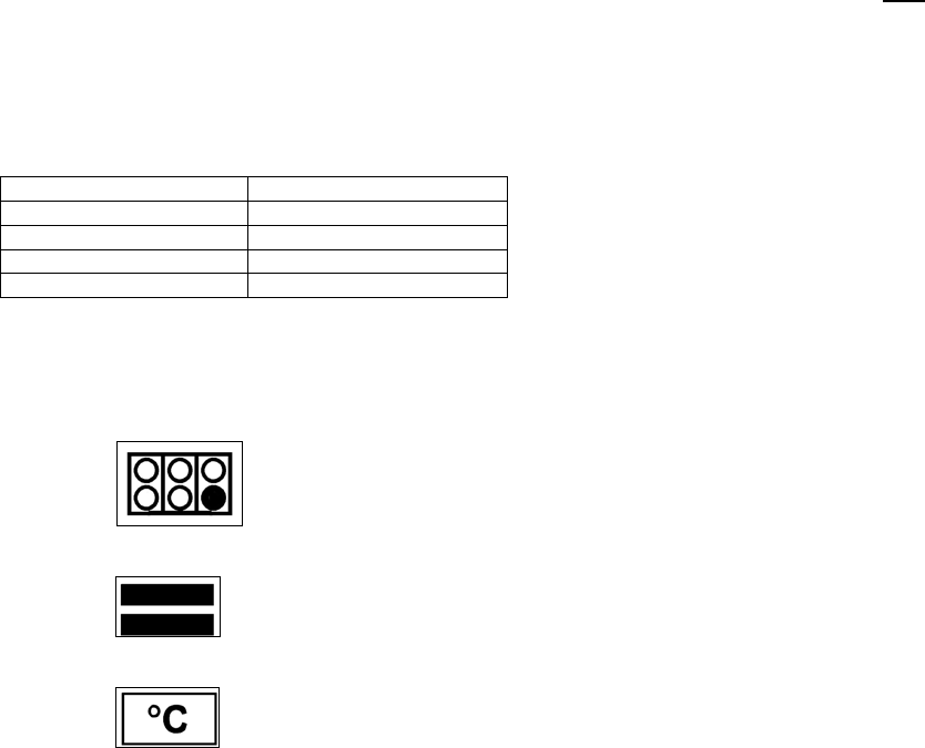
On the control panel, small symbols show the function of each knob or key. Here as follows are the several controls that
a cooker can have:
the symbol shows the disposition of burners on the worktop, the full dot identifies the burner in object (in
this case the front burner on the right).
the symbol
shows the running of any oven (ventilated gas oven with electric grill, 9 positions switch)
the symbol
shows the electric thermostat for electric oven
USING BURNERS
A diagram is etched on the control panel above each knob which indicates which burner corresponds to that knob. The
burners can be ignited in different ways depending on the type of appliance and its specific characteristics:
- Manual lighting (it is always possible even when the power is cut off): Turn the knob anticlockwise that
corresponds to the burner selected, setting it to the MAXIMUM position at the etched star (large flame Fig.23) and place
a lit match up to the burner.
- Electric ignition:
Turn the knob counterclockwise that corresponds to the burner selected, setting it to the MAXIMUM
position (large flame Fig. 23) and keep on pressing the knob in correspondence of the ignition symbol marked with a star
(for cookers equipped with ignition trough knob) or press the ignition button marked with a star and release it as soon as
the burner has ignited.
- Burner ignition equipped with safety device (thermocouple)(fig.24): Turn the knob anticlockwise that corresponds
to the burner selected, setting it to the MAXIMUM position at the etched star (large flame Fig. 23), press the knob and
activate one of the above-mentioned ignition devices. Once ignited, keep pressing the knob for about 10 seconds to
allow the flame to heat the thermocouple. If the burner goes out after releasing the knob, repeat the entire operation.


