


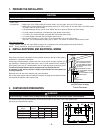
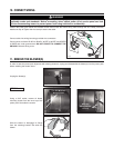
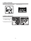
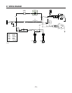
2. INSTALL DUCTWORK AND ELECTRICAL WIRING
Plan where and how the ductwork will be installed. Access to the top of the hood is
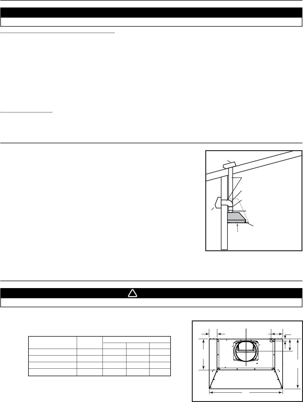
preferred for connection of ductwork.
Install proper-sized ductwork, elbows and roof or wall cap for the type of blower you
are installing. If installing CP35 power pack, use 8” round ductwork and if installing
CP37 power pack, use 10” round ductwork. Use 2” metal duct tape to seal duct joints.
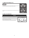
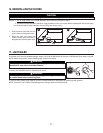
The minimum hood distance above cooktop must not be less than 24”.
A maximum of 30” above cooktop is highly recommended for best capture of
cooking impurities.
Distances over 30” are at the installer and users discretion.
Run 3-wire power supply cable to installation location. Its length should extend at least
4 feet below the bottom of the custom hood.
Power pack
Roof cap
Wall
cap
HH0101A
8” round duct for CP35 or
10” round duct for CP37
8” round adapter & damper
for CP35 or
10” round adapter for CP37
24” to 30”
above
cooking surface
8” round elbow for CP35 or
10” round elbow for CP37
10” in line
vertical damper for CP37
MODEL CP35 (SINGLE BLOWER)
OR CP37 (DUAL BLOWER)
TYPICAL DUCTWORK
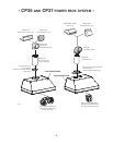
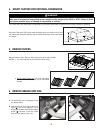
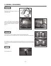
1. PREPARE THE INSTALLATION
Make sure that the following items are included:
- Power Pack
- Accessories: • Baffle filters (3 for CP35 model 30’’ and 36’’ width, 4 for 42’’ width, and 5 for CP37 model)
• Baffle filters handles (taped inside the power pack) (3 for CP35 model 30’’ and 36’’ width, 4 for CP35 model
42’’ width, and 5 for CP37 model)
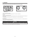
• 2 Shielded halogen lamps (120 V, 50 W, MR16 with GU10 base or PAR16 with GU10 base)
• 8” round adapter and damper (included with single blower power pack)
• 10” round in-line vertical damper (included with dual blower power pack)
• 10” round adapter (included with dual blower power pack)
• Bag of parts including: (1) wire clamp, (2) wire connectors, (4) no. 8 x 3/8” screws,
(9) no. 8 x 1/2” chrome plated screws, (10) no. 8-32 x 1/4” screws. If need be, discard extra screws.
Parts sold separately:
- Ducts, elbows, wall and roof caps. Refer to page 3 for a complete list of venting options and model numbers.
NOTE: During installation, protect countertop and/or cooktop.
CAUTION
When performing installation, servicing or cleaning the unit, it is recommended to wear safety glasses and gloves.
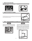
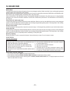
3. CUSTOM HOOD PREPARATION
WARNING
When building a custom hood, always follow all applicable construction codes and standards.
!
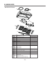
The custom hood must be constructed to fit the size and shape of the CP35 or the CP37 power pack.
See chart and illustration for details.
* Dimensions A and B include rivets head.
POWER PACK TOTAL DIMENSIONS
MODEL WEIGHT A* B* C
CP35 (30”
WIDTH) 33 LB 19
5
⁄16” 28
7
⁄16”4
7
⁄8”
CP35 (36”
WIDTH) 37.2 LB 19
5
⁄16” 34
7
⁄16”4
7
⁄8”
CP35 (42” WIDTH) 41.6 LB 19
5
⁄16” 40
7
⁄16”4
7
⁄8”
CP37 (48”
WIDTH) 56.5 LB 22
9
⁄16” 46
7
⁄16”5
7
⁄8”
A
B
C
7/8
”
4½”
HD0296A
C
L
12”
3”
REAR
FRONT
- 4 -