


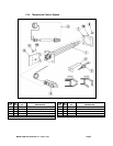
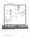
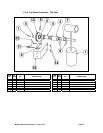
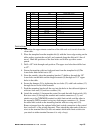
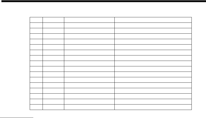
QTY
P/N
DESCRIPTION
1 12 FT 00400.00 Conduit 3/8 sealtite
2 1 00401.00 ST-3/8 strai
g
ht connecto
r
3 1 00402.00 ST-90 de
g
.3/8 connecto
r
4 2 00666.00 Fork ton
g
ue connecto
r
5 24 FT 00529.00 Wire 18
g
au
g
e blac
k
6 1 13427.60 Tem
p
late ki
t
7 1 13427.61 Mountin
g
bracke
t
8 1 13427.62 Actuato
r
9 1 13427.63 Bum
p
e
r
10 2 03817.00 6-32 win
g
nu
t
11 2 03814.10 Lock star washe
r
12 2 00914.10 1/4-20 x 5/8 hexhead bol
t
13 2 00968.00 1/4 s
p
lit lock washe
r
14 2 00924.00 1/4 ss washe
r
15 2 00912.00 1/4-20 n
y
lon lock nu
t
16 1 13427.10 Limit switch
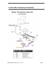
Instructions:
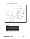
1. Determine the approximate centerline of the dish rack as it travels down the
clean table.
2. Place the template from the template kit (6) with the lower edge resting on the
table surface, against the end roll, and centered along the dish rack’s line of
travel. Mark the positions of the four holes and follow up with a center
punch.
3. Drill a 1/8” hole through each position .The upper two holes then drilled out
to1/2”.
4. Fasten the template with two bolts and nuts from the template kit (6).The
lower holes then drilled out to 3/8”.
5. From the outside, place the mounting bracket (7) halfway through the 3/8”
lower holes on the table and the hinged actuator (8) through two 1/2” upper
holes in the table.
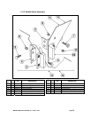
6. Secure the bumper (9) by tightening the two bolts (12) with lock washers (13)
through the two holes in the actuator.
7. Push the mounting bracket all the way into the holes in the table and tighten it
with two lock nuts (15) and two washers (14).
8. Attach the conduit (1) between the control box and the table limit switch (16).
Run two wires (5) through the conduit and conduit connectors (2,3), and
attach one to the COMMON terminal on table limit switch, and the other to
the normally OPEN terminal, using two fork tongue connectors (4). Secure
the table limit switch on the mounting bracket with two wing nuts (10).
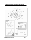
Remove jumper from the optional table limit switch connection in the control
box (see note 1 of the wiring diagram). Then, attach the other ends of the two
wires to the terminal block (it does not matter which table limit switch wire
you attach to either terminal because it is only a loop).
MODEL CMA-66 Part Manual rev. 1.06 01/11/05 Page 18