


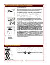
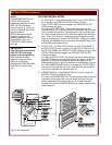
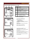
FILTERS INSTALLATION
1. FILTER PACK: Ships installed in the hood. If the FILTER PACK is
not in position, the CHECK FILTERS indicator will light.
If the FILTER PACK becomes clogged, the REPLACE FILTER
PACK indicator will glow.
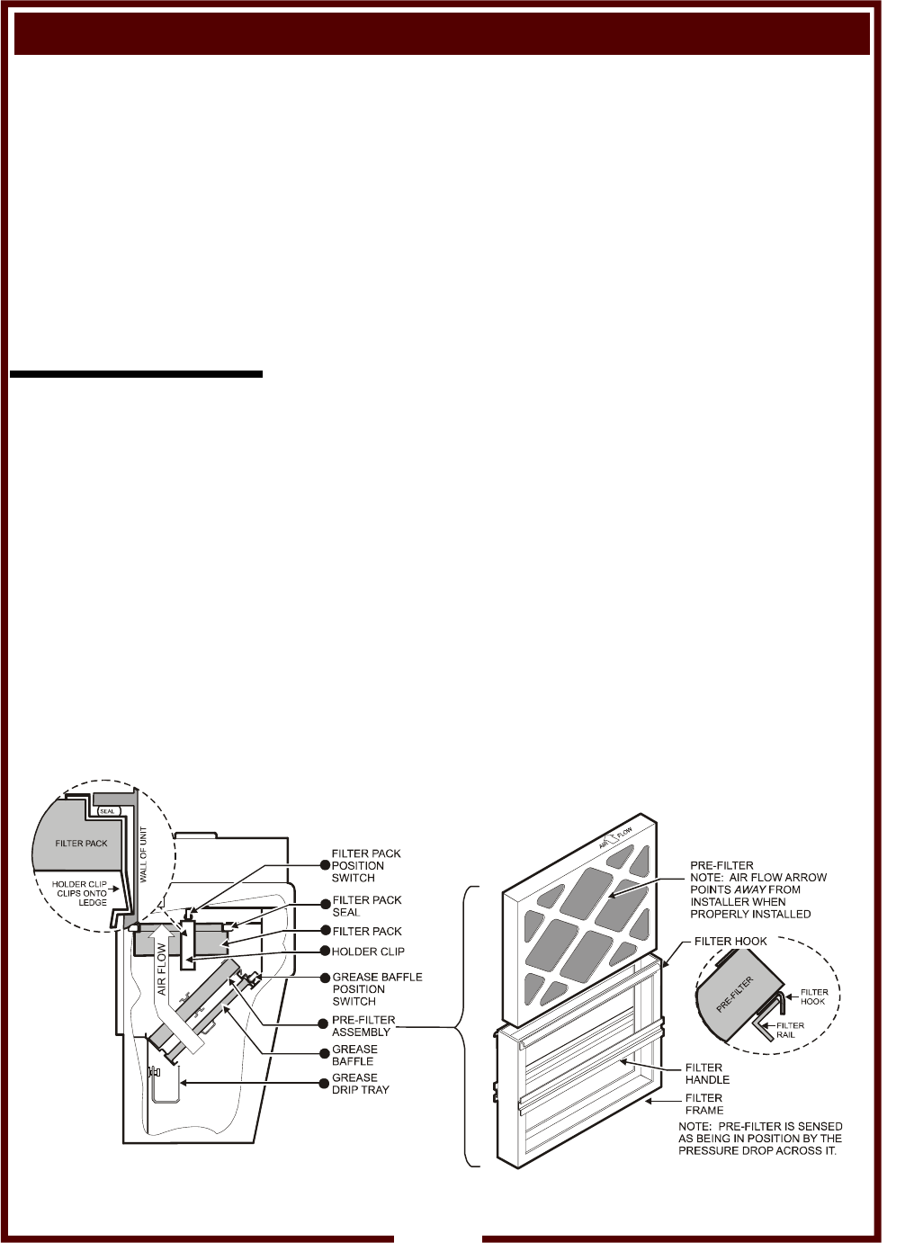
To install the FILTER PACK: Position the filter pack with the
charcoal portion UP. Slide the filter pack toward the rear of the unit
until it contacts the guides on the back panel. Push the filter pack
UP into the upper opening until it rests firmly against the filter pack
seal. When up in position, holder clips can be snapped over wall
ledge on each side. To remove FILTER PACK: Grasp both holder
clips and pull INWARD until the clips clear the sidewall ledge. Then,
pull the filter pack down and out.
2. PRE-FILTER: The PRE-FILTER ships in the FILTER FRAME. If
the PRE-FILTER is not in position, or if the PRE-FILTER is not in
the FILTER FRAME, the CHECK FILTERS indicator will light. If the
PRE-FILTER becomes clogged, the REPLACE PRE-FILTER
indicator will glow.
To install the PRE-FILTER: Pay attention to the air flow markings.
The AIR FLOW arrow will point away from the installer. Slide the
assembly up into the front opening, behind the upper filter rail.
While pressing slightly against the bottom of the assembly, pull the
FILTER HANDLE toward you so as to engage the FILTER HOOK
over the lip of the top filter rail. Then lower and seat the assembly
into the top indentation of the lower filter rail.
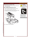
3. GREASE BAFFLE: If the GREASE BAFFLE is not in place, the
CHECK FILTERS indicator will glow.
To install the GREASE BAFFLE: Slide the grease baffle up into the
indentation of the upper filter rail, then lower and seat it into the
bottom indentation of the lower filter rail. Pull toward you and
downward to verify the GREASE BAFFLE is properly seated in the
lower frame rail.
NOTE:
The GREASE BAFFLE and
FILTER PACK activate
mechanical switches, and the
PRE-FILTER activates a
vacuum switch, to verify that
the filter elements are in their
proper positions.
All filter elements must be
properly installed or the
cooking appliances will not
be energized. Also, the
CHECK FILTERS indicator
will light.
IMPORTANT:
The filter hook prevents the
PRE-FILTER from being
drawn in during operation.
After installation, press
against the top of the filter
frame to verify proper
engagement of the filter hook
over the lip of the top filter
rail.
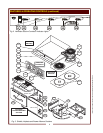
INSTALLATION (continued)
Fig. 6 Filter Installation
12
508 p/n 304456 OpManual WV-2H Series Ventless Combo Cook Center