H
39
Base Components – Front Accessible
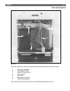
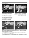
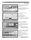
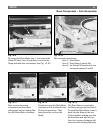
Fig. 10-3 Fig. 10-4
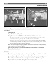
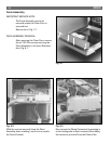
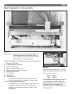
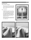
Fig. 10-5 Fig. 10-6
2
1
The front Leveling Legs can be adjusted by inserting a
regular tipped screwdriver into the foot slot and
turning the leg in the desired direction.
The Rear Leg Adjustment Screw, item 1, allows the
single Rear Leveling Leg to be adjusted from the front
of the unit. Turning the screw clockwise will extend
the leg, and counter-clockwise retracts it.
For convenience an additional Serial Number Tag,
item 2, is located on the Base.
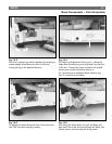
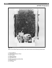
To replace the Water Solenoid Valve, first remove the
two T-20 Torx valve mounting screws.
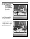
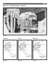
Then bring the Water Valve out from the Base, and
disconnect the water line by loosening the Water Line
Clamp (arrow) and removing the wiring leads.


