


4
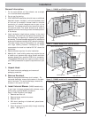
5. Mount the Hood
The DAH model hood can be mounted through the
back wall or through the top. See General Information,
page 1, for suggestions for hood height.
Once the preferred height is determined, locate the
centerline (left to right) of the cooking appliance.
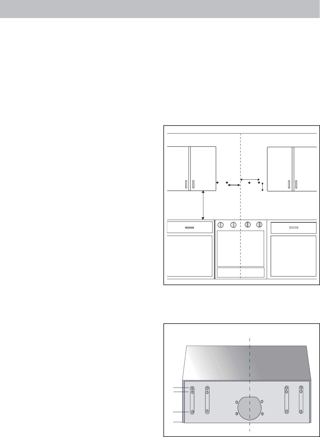
Wall Mount
1. From the centerpoint of the cooking appliance,
measure up to the preferred height. Measure up an
additional 9” to locate the centerline of the screw
holes (see Figure 4).
2. Install toggle bolts through drywall leaving 1/4” of
the bolt exposed.
Install one togglebolt 11 1/2” to the left of the
centerline and one togglebolt 11 1/2” to the right
of the centerline. These are the only installation
points for the 30” hood. See Figure 4
For the 36” hood, there are 2 additional installation
points. These are also at the centerline height, but
are 15 3/8” from the centerline in each direction.
See Figure 4.
3. Place the hood by sliding the mounting holes in the
hood over the bolts.
4. Tighten the bolts.
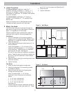
Top Mount
1. Install the hood flush against the back wall.
2. Identify the centerline on the mounting surface
(underside of cabinet).
3. Place the hood and install the drywall screws
through the mounting holes.
Insert 3 drywall screws 11 1/2” off the
centerline in both directions at the following
depths:
1. 2 1/4” from the back wall
2. 8 1/4” from the back wall
3. 9 1/4” from the back wall
(See Figure 5).
The 36” hood also requires 3 additional screws, at
the same depths, on each side (total of 6). These
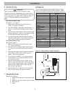
4. Install Transition
For internal blower installation, install the 7”
transition (included) to connect to 7” ducting. If 7”
ducting is not available, 8” ducting may be used. In
this instance, an additional 7-8” transition must also be
used (not included).
For remote blower applications, 10” ducting is
required. In this instance, a 7”-10” transition must
also be used.
Attach the transition with 4 #8 sheetmetal screws
(included) and seal connection with duct tape.
Installation
are 15 3/4” from the center line (See Figure 5).
4. Place the hood.
5. Tighten the screws.
Figure 4 - Wall Mount
Figure 5 - Top Mount
C
L
30" - 36"
11-1/2"
from CL
15-3/8"
from CL
9"
CL
1"
6"
2 1/4"
Top Mount
Back
Front