


22
Electrical connection
This is what you have to do:
1.Connect the green and yellow (Earth)
wire to the terminal in the plug marked
‘E’ or with the symbol ( ), or
coloured green or green and yellow.
2.Connect the blue (Neutral) wire to the
terminal in the plug marked ‘N’ or
coloured black.
3.Connect the brown (Live) wire to the
terminal marked ‘L’, or coloured red.
The extractor hood should only be
connected to an earthed socket that has
been installed according to relevant
regulations.
If possible, site the earthed socket directly
behind the chimney panelling.
Electrical data:
Are to be found on the name plate inside
the appliance after removal of the filter
frame.
ṇ Before undertaking any repairs,
always disconnect the extractor hood from
the electricity supply.
Length of the connecting cable: 1.30 m.
If it is necessary to wire the extractor
hood directly into the mains:
The extractor hood should only be
connected to the electricity supply by a
properly qualified electrician.
A separator must be installed in the
household circuit. A suitable separator is a
switch that has a contact gap of more than
3 mm and interrupts all poles. Such
devices include circuit breakers and
contactors.
ṇ If the connecting cable for this
appliance is damaged, the cable must be
replaced by the manufacturer or his
customer service or a similarly qualified
person in order to prevent serious injury to
the user.
This extractor hood corresponds to EC
regulations concerning RF interference
suppression.
Electrical connection
WARNING: THIS APPLIANCE MUST BE
EARTHED
IMPORTANT: Fitting a Different Plug:
The wires in the mains lead are coloured in
accordance with the following code:
Green and Yellow – Earth
Blue – Neutral
Brown – Live
If you fit your own plug, the colours of
these wires may not correspond with the
identifying marks on the plug terminals.
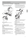
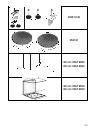
Prior to installation
Circulating-air mode
❑ With activated carbon filter if exhaust-air
mode is not possible.
ṇ The complete installation set can be
obtained from specialist outlets.
The corresponding accessory numbers can
be found at the end of these operating
instructions.
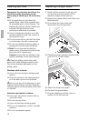
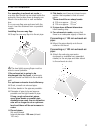
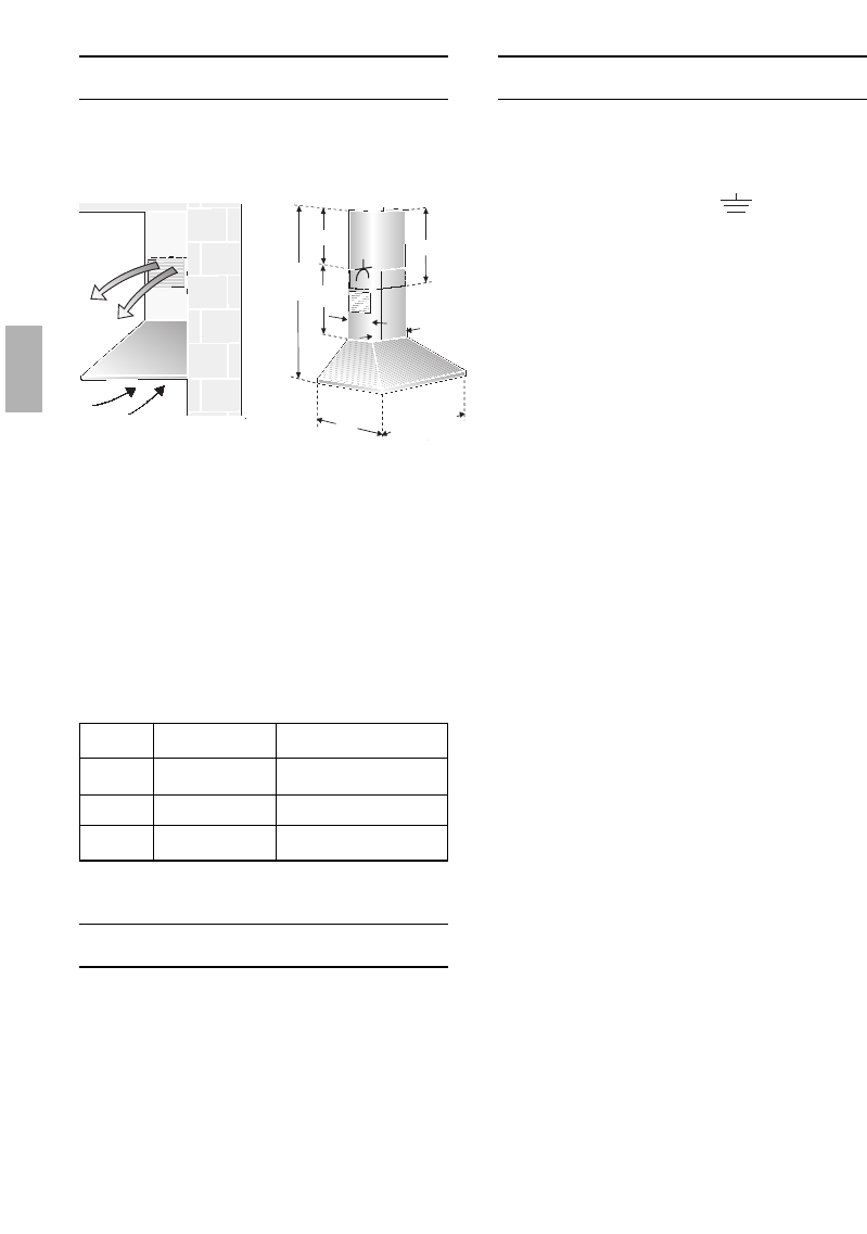
Preparing the wall
❑ The wall must be flat and perpendicular.
❑ Ensure that the wall is capable of
providing a firm hold for mounting
screws and plugs.
-
r
-
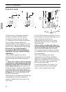
51-318
max. 1080
mind. 813
170
250
323
5
0
0
6
0
0
/7
0
0
/ 9
0
0
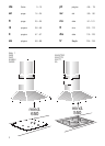
522
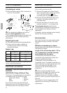
Weight in kg:
Exhaust air Recirculating air
12,560 cm
70 cm
13,5
13,0 14,0
90 cm 13,9 14,9
We reserve the right to construction changes within the
context of technical development.