


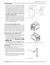


5AQ4 Manual
2 AQ4 Installation instructions
2.1 Introduction
Please follow these instructions. Failure to follow
instructions may result in:
· Damage, injury or death
· Improper operation
· Loss of warranty
If you are unable to perform the tasks required to
install the water heater and this accessory properly,
please contact a locally licensed plumber, HVAC
contractor or gas technician.
Please contact Bosch Water Heating with any
questions.
2.2 Locating power vent hood and
clearances
The maximum vent length from the water heater to
the point of termination is 25 feet. If using more than
one 90° elbow, subtract 5 feet off the maximum
vent length for each additional elbow used. Maximum
of three elbows allowed.
The power vent motor must be installed
as close as possible to the VH1-4 vent
hood.
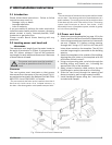
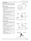
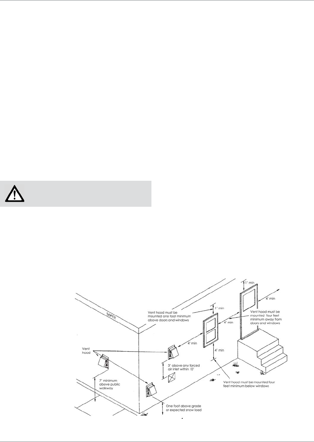
Clearances
The vent system must terminate so that proper
clearances from the center of the vent hood (Fig. 1)
are maintained as cited in the National Fuel Gas Code,
ANSI Z223.1 and CSA B149.1 in Canada:
“The vent terminal shall also not be installed closer than 3
feet from the inside corner of an L-shaped structure, or
less than 1 foot above grade or anticipated snow pack level.”
Also:
“The exit terminals of mechanical vent system shall be located
not less than 7 feet above grade when located adjacent to a
public walkway. The venting system shall terminate at least
3 feet above any forced air inlet within 10 feet. The venting
system shall terminate at least 4 feet below, 4 feet
horizontally from or 1 foot above any door, window or gravity
air inlet into any building.”
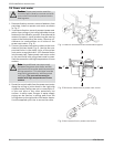
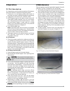
2.3 Power vent hood
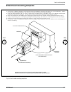
1. Attach the mounting template (on page 13) to the
interior wall that the vent hood will be penetrating.
2. Insure the proposed vent termination clearances
are met (Chapter 2.2) before cutting opening
through wall. Using a 1/2" drill bit, drill two pilot
holes where noted on the template. The drill bit
must be long enough to penetrate to the building
exterior.
3. Attach the template to the outside of the building
aligning the pilot holes on the template with the
pilot holes drilled in step 2.
4. Using a reciprocating saw, cut a hole through the
building siding, wall board, etc., following the
appropriate lines of the template.
5. Apply a bead of exterior-rated caulk to the vent
hood flange to seal at the exterior of building.
6. Slide the vent hood through the opening and
fasten to exterior wall using screws provided.
7. Install backdraft flapper using the instructions
included with flapper.
AQ4 Installation instructions
Fig. 1 External vent hood clearances