


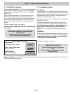

Ranges are dual rated for use on either 120/240 VAC or 120/208
VAC. See table for power ratings and circuit breaker sizes based
upon the supply voltage for each mode (See chart below).
4. Connect Electric
Step 4: Connect Electric
RISK OF ELECTRIC SHOCK FRAME GROUNDED TO NEUTRAL OF APPLIANCE THROUGH A LINK GROUNDING
THROUGH THE NEUTRAL CONDUCTOR IS PROHIBITED FOR NEW BRANCH-CIRCUIT INSTALLATIONS, (1996 NEC)
MOBILE HOMES AND RECREATIONAL VEHICLES, OR IN AN AREA WHERE LOCAL CODES PROHIBIT GROUNDING
THROUGH NEUTRAL CONDUCTOR. FOR INSTALLATIONS WHERE GROUNDING THROUGH THE NEUTRAL CONDUC-
TOR IS PROHIBITED:
(1) DISCONNECT THE LINK FROM THE NEUTRAL.
(2) USE GROUNDING TERMINAL OR LEAD TO GROUND UNIT: AND
(3) CONNECT NEUTRAL TERMINAL OR LEAD TO BRANCH CIRCUIT NEUTRAL IN USUAL MANNER
(WHEN THE APPLIANCE IS CONNECTED BY MEANS OF A CORD KIT, USE 4 CONDUCTOR
CORD FOR THIS PURPOSE).
WARNING
CONSULT YOUR INSTRUCTIONS FOR ‘ELECTRICAL CONNECTION PROCEDURES’. COPPER WIRE MUST BE USED
FOR CONNECTION TO THE TERMINAL BLOCK. WHEN POWER SUPPLY CORD KIT IS USED TO CONNECT RANGE TO
THE POWER SUPPLY. USE ONLY CORD KITS RATED 120/240 VOLTS MINIMUM AND MARKED FOR USE WITH RANGES.
REFER TO INSTALLATION INSTRUCTIONS FOR PROPER CORD KIT AMPERAGE RATING, RISK OF FIRE OR
ELECTRICAL SHOCK MAY BE INCURRED IF AN INCORRECT SIZE RANGE CORD KIT IS USED, THE INSTALLATION
INSTRUCTIONS ARE NOT FOLLOWED, OR THE STRAIN RELIEF BRACKET IS DISCARDED.
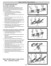
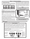
Figure 5
Remove ground
strap from terminal
block. Install with
care, the green
ground wire as
shown at left. Attach
ground wire and
strap with screw
provided with strap.
Center or white wire
must always be
attached to the
central terminal on
block.
All screw and nut
connections must be
tight.
Electrical Connection Procedures
Refer to Figures 5-10 ( below and next page) for further explanation.
Page 4
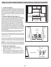
This appliance may be connected to the power supply by installing
flexible conduit or a power cord set. The electrical rating of the
power cord set (not supplied) must be 240 volt, 30 amperes. The
power cord set shall be marked “For Use with Ranges.”
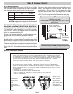
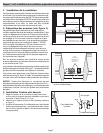
The power supply shall be connected to the range terminal block
compartment located near the bottom of the back panel (See
Figure 4 , at right). It is accessible by removing the terminal block
cover.
TO PREVENT ELECTRICAL SHOCK, THE GROUNDING PRONG
SHOULD NOT, UNDER ANY CIRCUMSTANCES, BE CUT OR RE-
MOVED. IT MUST BE PLUGGED INTO A MATCHING GROUNDING
TYPE RECEPTACLE AND CONNECTED TO A CORRECTLY POLAR-
IZED 240-VOLT CIRCUIT. A separate circuit is recommended
which is in compliance with the NEC.
If there is any doubt as to whether the wall receptacle is prop-
erly grounded, have it checked by a qualified electrician.
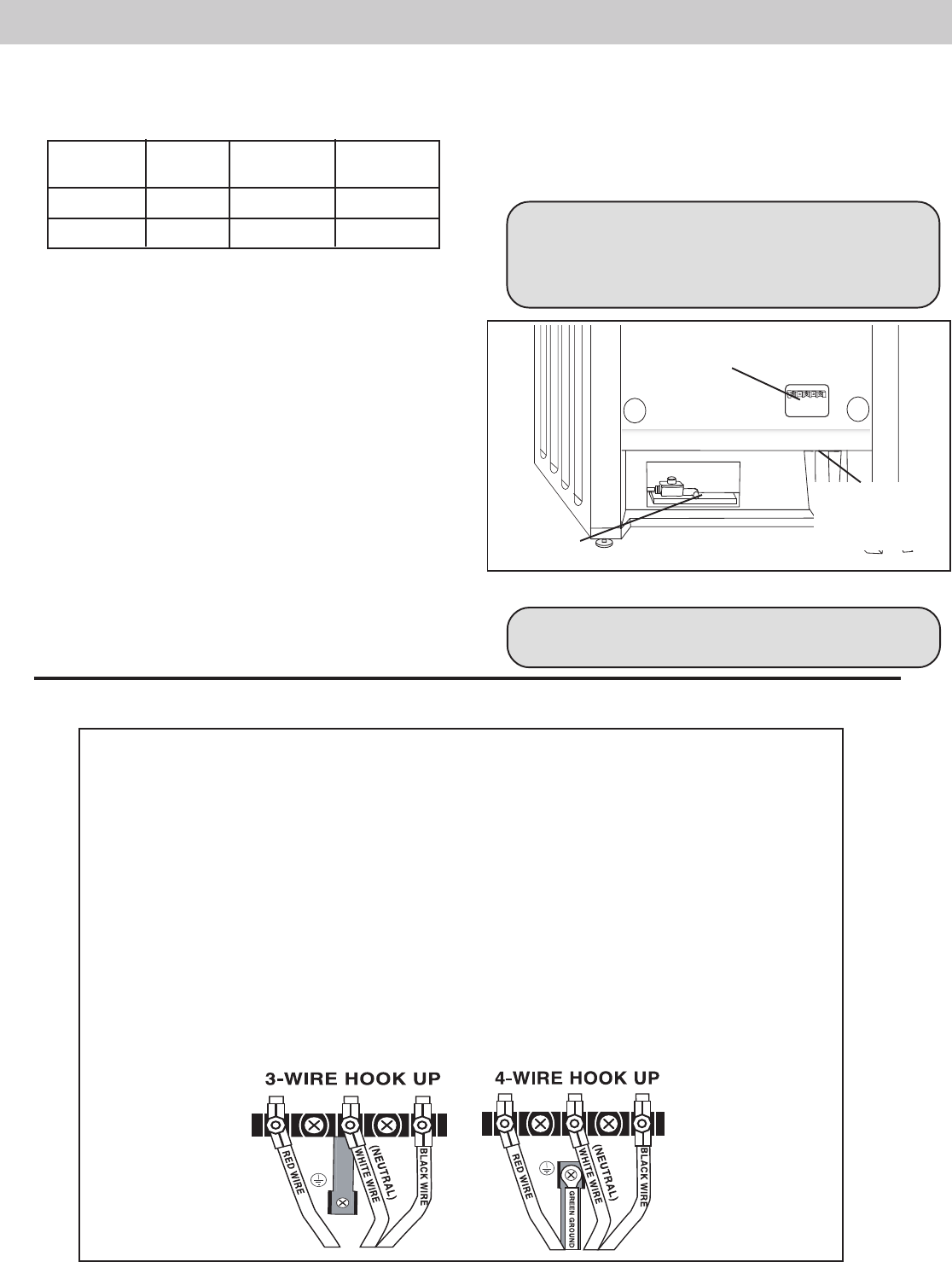
VOLTS HZ RATING CIRCUIT
A.C. KW BREAKER
120/240 60 12.1 30 AMPS
120/208 60 9.1 25 AMPS
CAUTION: make certain that gas shutoff valve and all
burner controls are in OFF position before beginning.
The strain relief provided with your range cord
must be properly installed.
Place strain relief in knockout below terminal block (See Figure
4
below). Feed range cord through hole and strain relief up to
terminal block. Allow for slack in the cord between the strain
releif and terminal block. Once cord length/ slack has been
adjusted, attach strain relief per instructrions included with strain
relief. Connect wiring as described below and on next page.
Figure 4
Electric Connection
(found behind terminal
block cover)
Gas Connection
Feed Range
Cord Through
Strain Relief in
Knockout
Panel Here
TIP
The knockout panel can be removed from the range to
install the strain relief:
Remove panel from range, install strain relief in panel
and re-attach.