


1. Install Ventilation
For the cabinets over the cooking surface and the adjacent cabinets,
the maximum cabinet depth from back wall is 13 inches.
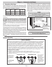
The gas supply line and electrical outlet must be within the spaces
indicated in Figure 2. The gas shut off valve must also be accessible
without moving the range.
Instructions were determined using Standard American base
cabinets measuring 36" high x 24" deep. If nonstandard cabinets
are used, care should be taken to alter dimensions accordingly.
NOTICE: Some cabinet finishes cannot survive the temperatures
allowed by U.L., particularly self-cleaning ovens; the cabinets may
discolor or stain. This is most noticeable with laminated cabinets.
Steps 1, 2, and 3: Install Ventilation, Prepare Cabinets, Install Anti-Tip Bracket
Page 3
It is strongly recommended to install a hood above this range. For
most kitchens with a wall mounted hood, a certified hood rating
of not less than 350 CFM is recommended. Bosch hoods rated at
350 CFM or more when operated on high meet the above
requirement and are recommended for this purpose. The range
hood must be installed according to instructions furnished with
the hood.
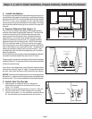
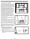
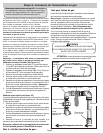
2. Prepare Cabinets (See Figure 1)
This unit can be installed near adjacent walls and projecting
surfaces constructed of combustible materials. There must be
a minimum clearance of 30 inches between the top of the
cooking surface and the bottom of an unprotected wood or
metal cabinet; or 24 inches when bottom of wood or metal
cabinet is protected by not less than 1/4" of flame retardant
material covered with not less than No. 28 MSG sheet metal,
0.015 inch stainless steel or 0.024 inch aluminum or copper.
Zero clearance from unit walls to adjacent vertical combustible
walls is permitted on rear, right and left walls. Clearance from
range top to adjacent vertical walls must be at least 4”. Seal
any openings in the wall behind the appliance and in the floor
below the appliance.
Figure 1: Cabinet Preparation
30” Minimum Centered
30” Min.
4” Min.
4” Min.
18” Min.
No Clearance to Cabinet
Wall Required
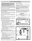
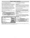
Figure 2: Gas Supply Line and Electrical Outlet Placement
7 1/2"
4 1/2"
13 1/8 "
4"
3 7/8"
4 1/2"
3 1/2"
30"
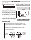
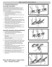
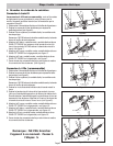
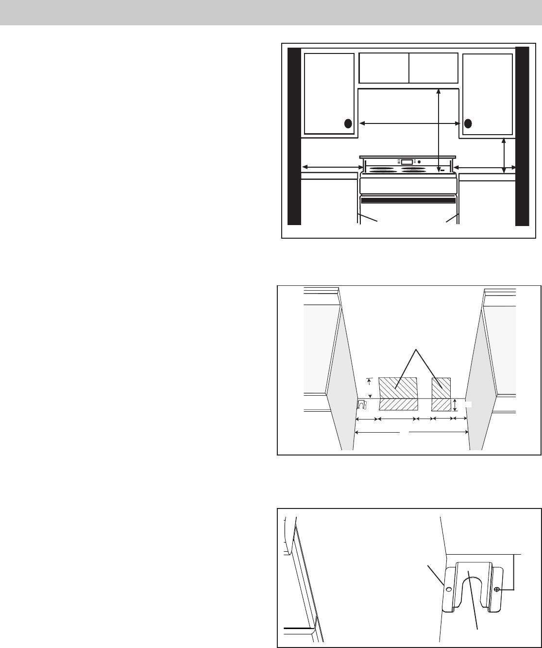
3. Install Anti-Tip Bracket
1. Adjust height of range and level by rotating the
adjustable leg supports on the bottom of the range,
using 1-1/4" wrench.
2. Measure to locate bracket position as shown in Figure 3.
3. Secure bracket with 2 screws adequate for mounting
surface, not included. (i.e.; for wood floor use wood screws
for concrete floor use concrete anchors and screws.).
Place Gas Supply
Line and
Electrical Outlet
Here
7 1/2”
4 1/2”
13 1/8”
4” 3 7/8”
3 1/2”
4 1/2”
30”
Figure 3
1 9/16”
Flush
Cabinet Sidewall
Anti-Tip Device
Backwall