


15
STEP 5:
INSTALL THE MOUNTING
PLATE TO THE WALL
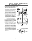
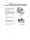
1. Draw a vertical line on the wall at the center of the 30″
wide space.
Use the mounting plate as the template for the rear
wall. Place the mounting plate on the wall, making sure
that the tabs are against the bottom of the cabinet. Line
up the notch and center line on the mounting plate to
the center line on the wall.
2. While holding the mounting plate with one hand, draw
circles on the wall at holes A, B, C and D. Four holes
must be used for mounting. If the holes are not used,
the installation will not be secure. Installer must use
these holes for proper installation. Use toggle bolts
through these holes unless one of them lines up with a
stud. Use a lag screw for studs.
For wall-vented: The oven requires a rear wall cutout
opening for the rear wall duct and the exhaust adaptor
must be attached to the mounting plate. See the next page
on how to prepare the rear wall cutout opening and the
exhaust adaptor/mounting plate for wall-vented.
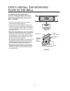
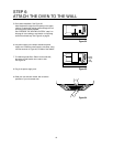
3. Drill holes on the circles. If there is a stud, drill a 3/16″
hole for lag screws. Two or preferably four lag screws
at holes A and C or B and D must be used to secure
mounting plate to wall. If there is no stud, drill a 3/4″
hole for toggle bolts. Make sure to use at least 1 lag
screw at holes of area “E” in a stud, and 4 toggle bolts
at holes A, B, C and D in the drywall or the plaster.
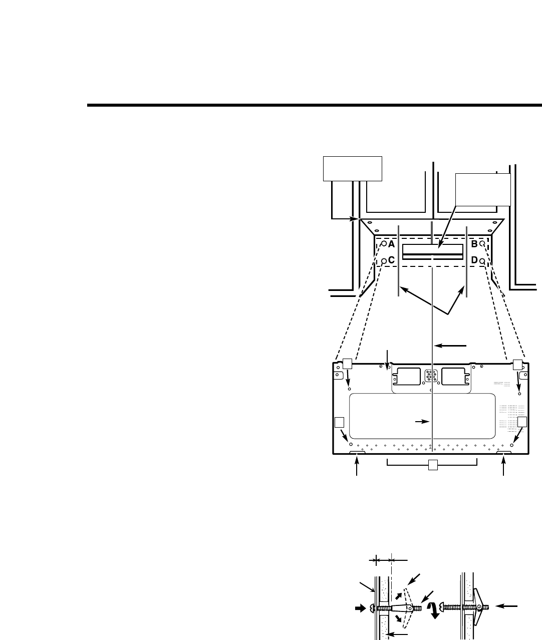
4. Attach the plate to the wall. To use spring toggle head
bolts: Remove the toggle wings from the bolts. Insert
the bolts into the mounting plate and replace the spring
toggle head to 3/4″ past the bolt ends. Insert the spring
toggle head into the holes in the wall to mount the
bracket. You may pull forward on the bracket to help in
tightening the toggle bolts. Tighten all bolts.
See Figure 27.
Center Line
A
C
B
3/16" Hole on Studs
3/4" Hole on Drywall Only
Draw
Center Line
Draw Lines
on Studs
Wall
Mounting
Plate
Space More Than Wall Thickness
Bolt
End
Toggle Bolt
Toggle Wings
For Wall-
Vented Only
Minimum 66
"
From the Floor
Support Tab Support Tab
E
Mounting
Plate
Figure 26
Figure 27
D
CONNECTING THE OVEN TO A WALL STUD:
NOTE: Draw a fifth circle inside area E, through one of
the holes to match the location of a stud.
NOTE: The oven must be connected to at least one
wall stud.