38
H
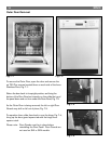
Base Components – Front Accessible
Fig. 10-2
Fig. 10-1
7
=
6
5
4
8
33
1
2
9
=
1
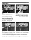
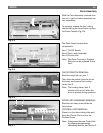
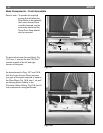
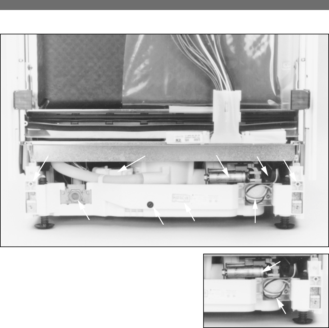
The electrical connection, item 1, is a three
wire hook-up that is secured with wire-nuts.
The color code is as follows:
Black = Hot
White = Neutral
Green = Ground
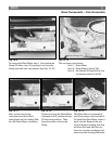
The Circulation Motor Capacitor, item 2, is
a 10uf-Start/Run Capacitor held to the
Circulation Motor with a single 13mm nut.
The Capacitor can be replaced as a
separate component without removing the
Circulation Motor.
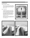
Service note: To gain access to the Front Accessible Lower
Components remove the Toe Kick. Also, for
better visibility it is strongly recommended that
the Outer Door be removed as well.
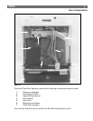
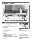
The Front Accessible Lower Components consist of the following items.
1. Electrical Connection.
2. Circulation Motor Capacitor.
3. Front Leveling Legs.
4. Model and Serial number tag.
5. Rear Leveling Leg adjustment screw.
6. Water Solenoid Valve.
7. Access Panel.
8. Drain Motor.
9. Circulation Motor.
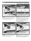
The Circulation Motor cannot be replaced from the
front, but is accessible for voltage or wiring testing.
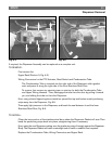
10. Door Spring Adjustment Screws.
The adjustment can only be made when an accessory
door panel is added to the unit. Turning the screw
clockwise will balance the additional weight of the
added panel.
2


