


2
ROOF CAP
ROOF CAP
REMOVE THE
HOOD DAMPER
FLAP IF IT IN-
TERFERES WITH
THE WALL CAP
DAMPER
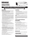
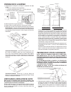
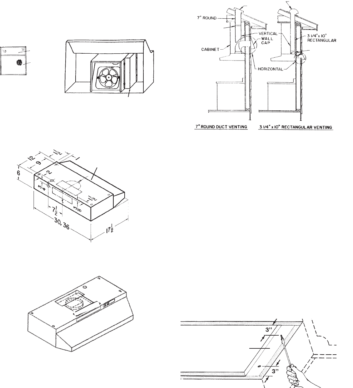
Ducting directly through the wall (for range hoods mounted
on an exterior wall). Shown are two ways to duct through an
outside wall. If a wall cap is used directly off the back of the
hood, special care must be taken to make sure that the damper
in the damper/duct connector on the hood and damper in the
wall cap do not interfere with each other when the hood is
operating. This could result in either inadequate air delivery
or back drafts. If this condition does exist, remove the hood
damper flap. Sometimes when using a wall cap, it is easier to
duct vertically and then use an elbow.
Ducting straight up through roof using 3-1/4" x 10" or 7" round
duct. For single story installations.
Ducting between ceiling joists for multi-story installations or
through soffits above cabinets where soffit connects to outside
walls.
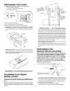
PREPARING THE
INSTALLATION LOCATION
NOTE: MOUNT HOOD SO THAT BOTTOM OF HOOD IS 18"
TO 25" ABOVE COOKING SURFACE. TOP FRONT OF HOOD
SHOULD BE FLUSH WITH FRONT OF CABINET FRAME.
IF DISTANCE BETWEEN WALL AND FRONT OF CABINET
FRAME IS MORE THAN 12", THERE WILL BE A SPACE BE-
TWEEN BACK OF HOOD AND WALL. THIS IS NORMAL.
OMIT STEP 1 IF HOOD WILL BE INSTALLED UNDER CABI-
NETS WITH FLUSH BOTTOM.
1. Fo r cabinets with recessed bottoms only: Install wood filler
strips on each side of recessed area under cabinet. Use two
1" x 2" strips cut to length (use thicker strips if necessary).
Fasten strips with wood screws about 3" in from each end.
2. Measure and mark the following:
a.) Electrical wiring opening in wall
or cabinet.
b.) Duct opening in wall or cabinet (vented hoods only).
FILLER STRIP
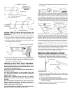
DAMPER
(INCLUDED)
BP87 DAMPER (NOT IN-
CLUDED) LOCATED AT
LEAST 6" FROM HOOD
IN VERTICAL SECTION
OF DUCT
LIGHT LENS
ALUMINUM OR
COMBINATION
FILTER
JUNCTION BOX
VENT COVER
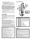
PREPARING THE HOOD
1. Unpack hood and check contents. You should receive:
1 – Filter with built-in light lens
1 – 3-1/4" x 10" damper/duct connector
1 – Installation parts bag
2. Remove junction box cover.
3. Remove top or rear electrical knockout.
4. Select one of the three types of venting available:
Non-Vented — Remove vent cover from hood front. Replace
the aluminum filter with a non-ducted filter (BP57 or R610050
- purchase separately). Go to "Preparing the Installation Loca-
tion".
Rectangular Vented — 3-1/4" x 10" vertical or horizontal. Re-
move knockout #② for vertical or knockout #③ for horizontal
venting. Install damper/duct connector over opening. Go to
"Planning Ductwork Installation".
Round Vented — 7" vertical. Remove knockouts #① and #②
exposing duct collar. Go to "Planning Ductwork Installation".
PLANNING DUCTWORK
INSTALLATION
This section for vented hoods only. Non-vented hoods skip
this section and go on to "Preparing the Installation Loca-
tion".
Begin planning ductwork by deciding where duct will run between
hood and outside. For best performance, use shortest possible
duct run and a minimum number of elbows. There are several
choices.
①
②
③