


6
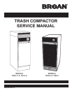
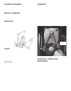
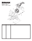
SWITCH LOCATIONS
KEY SWITCH
1. Remove control panel.
2. Remove two hex head screws supporting control panel brack-
et with 5/16" socket.
3. Pull bracket out and remove switch.
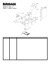
UPPER LIMIT SWITCH
1. Remove drawer assembly .
2. Lower ram to gain access to switch.
3. Remove air scentry tray.
4. Remove hex head screw with 5/16" socket, pull switch down
and disconnect wires.
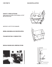
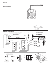
Check Switch not Switch
Continuity Activated Activated
3 to 1 closed op en
2 to 1 op en closed
6 to 1 o p e n o p e n
3 to 4 o p e n o p e n
6 to 4 closed op en
5 to 7 op en closed
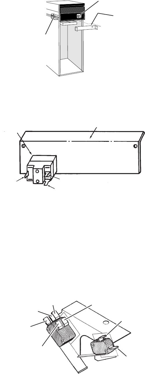
INTERLOCK SWITCH
The interlock switch is a single-pole, single-throw momentary
type. It is located on the right side behind the air scentry panel.
Its contacts are normally open. the contacts close when the door
is closed. It is activated by the actuator located on the back of
the door. Another switch located against the interlock switch is
to provide the “No-Jam” circuitry function. This switch is nor-
mally open and bypasses the interlock to provide “No-Jam”
capability. It can be replaced in the same manner as the inter-
lock switch.
TO REPLACE INTERLOCK SWITCH
1. Remove air scentry panel assembly.
2. Disconnect leads one by one and attach to new switch.
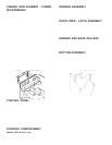
TRUNNION NUT
1. Remove back panel, drawer assembly and air scentry panel.
2. Lower ram manually to approx. 10-1/2" from the bottom
assembly onto box or stand described in “CABINET RE-
PLACEMENT/POWER P ACK REMOVAL” section.
3. Remove screws from nut retainer .
4. Raise ram assembly slightly by hand and remove nut.
NOTE: Count the number of revolutions to spin off nut. TRUN-
NION must be reinstalled to same position.
5. Reinstall trunnion nut and retainer.
CONTINUAL STRIPPING OF TRUNNION NUT:
POSSIBLE CAUSES:
1. Incorrect assembly of trunnion assembly.
2. Transporting compactor incorrectly.
3. Burr on main drive screw; sharp edge on lead-in thread.
4. Upper limit switch adjustment.
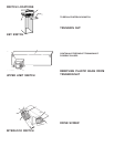
REMOVING PLASTIC BAGS FROM
TRUNNION NUT
Only the trash compactor bags specifically designed and sold
by Broan for use in the compactor should be used. Regular
plastic garbage bags used in place of the Broan bags may be
drawn into the mechanism. Removal of those bags is not cov-
ered by the warranty.
To remove bag from trunnion nut:
1. Remove back of compactor.
2. If possible to slide drawer slightly, remove the door by slid-
ing out the two hinge pins and then prying the door over the
lip on the drawer.
3. Liberally spray drive screw and trunnion nut with WD-40
R
or similar .
4. Use 15/16" socket, and extension, and a 16" ratchet (for le-
verage) and manually turn the drive screw clockwise. (See
section on manually raising and lowering ram.) By turning
the drive screw clockwise, you will help back the bag out of
the trunnion nut.
5. After removing bag, clean drive screw and regrease it with
wheel bearing grease.
DRIVE SCREW
1. Lower ram manually approximately halfway.
2. Remove sprocket.
3. Remove 1/4" drive pin. Slide off washers.
4. Lift ram, causing drive screw to slide out of the motor trun-
nion bearing. Support motor/gearbox assembly since it is
now free to pivot. Unscrew drive screw from front trunnion
assembly.
KEY
SWITCH
CONTROL PANEL BRACKET
V-BLACK
TR-RED
Y-BLUE
INTERLOCK
SWITCH
KEY SWITCH
UPPER LIMIT
SWITCH
1-STRIPED BLUE
7-BROWN
2-ORANGE
3-VIOLET
6-YELLOW
4-BROWN
5-YELLOW