


2
CONNECT DUCTWORK
Ducted Configuration
1. Take the damper and assemble it onto the hood’s discharge
opening, pressing slightly.
2. Use 6" round metal duct to connect the discharge collar on the
hood to the ductwork above.
3. Use duct tape to make all joints secure and air tight.
Non-Ducted Recirculation Configuration
1. Connect a 6” round metal duct to the discharge opening so
that the air is sent outside the cabinet and sent back into the
room.
2. Use duct tape to make all joints secure and air tight.
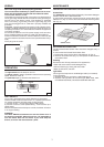
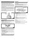
NON-DUCTED RECIRCULATION FILTER
INSTALLATION
1. Remove the metal wires (Fig. 9) and discard them.
2. Install the Non-ducted recirculation filter over the grease filter and
secure it with the metal wires supplied with the Non-ducted
recirculation Filter (Fig. 6).
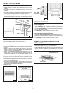
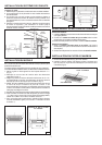
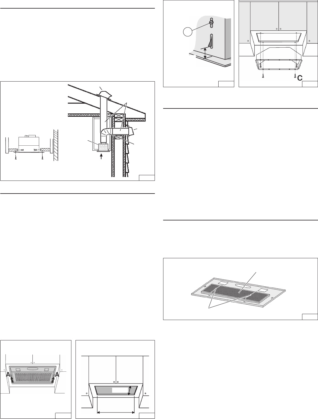
INSTALL THE DUCTWORK
NOTE: To reduce the risk of fire, use only metal ductwork.
1. Decide where the ductwork will run between the hood and the
outside.
2. A straight, short duct run will allow the hood to perform most
efficiently.
3. Long duct runs, elbows, and transitions will reduce the performance
of the hood. Use as few of them as possible. Larger ducting may
be required for best performance with longer duct runs.
4. Install a roof or wall cap. Connect round metal ductwork to cap
and work back towards hood location. Use duct tape to seal the
joints between ductwork sections.
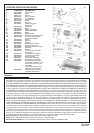
INSTALL THE HOOD
NOTE: the hood has to be installed, inside the cabinet, at minimum
1” from the rear wall cabinet and at 3” from the front wall cabinet.
The internal height of cabinet has to be minimum 16”.
The hood should be mounted centered over the cook top burners.
1. Remove the grid by moving the 2 slide fasteners “A” forward (Fig.2).
2. Cut a hole in the bottom of the cabinet, using the dimensions shown
(Fig. 3).
3. Adjust the position of the clasping side spring by means of the
proper “B” screw according to the thickness of the bored panel to
which it is going to be anchored (Fig. 4).
4. NOTE: For installations where the Power Pack is less than 30”
above cook top, it is recommended that the Power Pack be
mounted into a metal liner or non-combustible material. This will
allow easier cleaning and provide protection to the cabinetry.
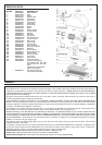
5. Insert the hood in the cabinet and lock it by means of the side
spring.
6. Insert the hood in the cabinet and secure with the (4) “C” mounting
screws 3.2x13mm (Fig. 5). For alternative side fixing use M4x15mm
screws with washers and nuts.
7. In the Non-Ducted Recirculation Configuration, install the Non-
ducted recirculation Filter before replacing the grid (see section
“Non-ducted recirculation filter installation”).
8. Replace the grid.
ROOF CAP
ROUND
DUCT
WALL
CAP
6”
ROUND
ELBOW
24” TO 30” ABOVE
COOKING SURFACE
CUT A HOLE IN THE BOTTOM OF
THE CABINET
10-1/4”
19-1/2”
POWER
MODULE
min 7/16”
max 13/16”
B
FIG. 6
FIG. 1
FIG. 2 FIG. 3
FIG. 4 FIG. 5
NON-DUCTED
RECIRCULATION FILTER
METAL WIRES