


MODELS QP142SS • QP142WW • QP142BL
Page 3
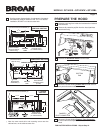
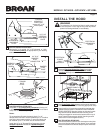
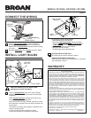
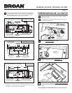
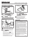
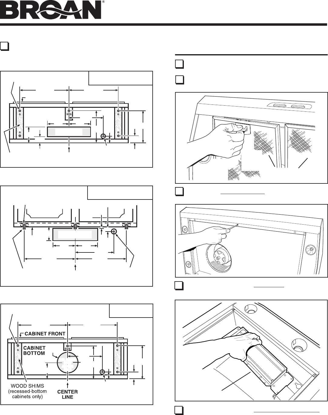
ELECTRICAL
ACCESS HOLE
(in cabinet bottom)
17
5
/8"
2
1
/8"
17
5
/8"
6
7
/8"
10
7
/8"
2
5
/8"
HOOD MOUNTING SCREWS (5)
4
5
/8"
8" DIA.
HOLE
7-IN. ROUND
DUCT
ACCESS
HOLE
7-IN. ROUND
DUCT
ACCESS
HOLE
11"
*
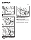
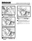
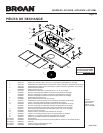
PREPARE THE HOOD
7 Remove 2 Screws holding Damper / Duct Connector
to hood. Remove damper/duct connector from inside the
hood.
FOR DUCTED INSTALLATIONS - Skip to Step 12.
DAMPER /
DUCT CONNECTOR
ALUMINUM
FILTERS
5 Remove the Aluminum Filters from the hood.
ç
4 Remove all protective polyfilm from the hood (stainless
steel hoods only).
3 Remove parts bag from inside the hardware box included
with the hood.
6 Remove 6 Screws holding Bottom Pan to hood. Set bot-
tom pan and screws aside.
(1)
PULL
DOWN
(2)
LIFT
OUT
ç
*
Note the extra wood shim and mounting screw near the
cabinetfront,onthecabinetcenterline.
BOTTOM
PAN
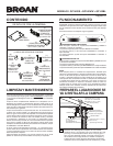
3¼” X 10”
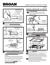
HORIZONTAL DUCTING
CABINET
BOTTOM
CABINET FRONT
HORIZONTAL DUCT
ACCESS HOLE
5¼"
5¼"
HOOD
MOUNTING
SCREWS (5)
ELECTRICAL
ACCESS HOLE
(in wall)
4"
CENTER
LINE
WOOD SHIMS
(recessed-bottom
cabinets only)
17
5
/8" 17
5
/8"
6
7
/8"
1
3
/8"
3
/8"
*
7” ROUND
DUCTING
VERTICAL DUCT
ACCESS HOLE
¾"
10
7
/
8
"
5¼"
5¼"
CENTER
LINE
HOOD MOUNTING SCREWS (5)
ELECTRICAL
ACCESS HOLE
(in cabinet bottom)
WOOD SHIMS
(recessed-bottom
cabinets only)
CABINET FRONT
CABINET
BOTTOM
17
5
/
8
"
4½"
2
1
/
8
"
17
5
/
8
"
2
5
/
8
"
11"
6
7
/
8
"
*
3¼” X 10”
VERTICAL DUCTING
2 Use the proper diagram below, for placement of ductwork
and electrical cutout in cabinet or wall. For a non-ducted
installation, DO NOT cut a duct access hole.