


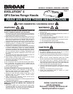
MODELS QP430SS • QP436SS • QP442SS
Page 7
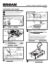
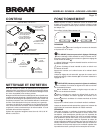
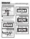
11 Run House Power Cable between service panel and hood
location. Attach power cable to hood using appropriate clamp.
12
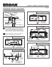
Hang hood from (4) mounting screws driven part-way into
cabinet locations (shown in illustrations under “PREPARE
HOOD LOCATION”). Mounting screws are included in
parts bag. Slide hood back towards wall until mounting
screw heads are engaged in narrow end of keyhole slots
in top of hood. Tighten screws securely. Add 5th mounting
screw in center hole in hood and tighten securely.
13
Connect ductwork to hood and use duct tape to make
joints secure and air-tight. Make sure the damper / duct
connector enters the ductwork and that the damper opens
and closes freely.
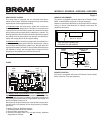
HOUSE
POWER CABLE
INSTALL THE HOOD
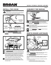
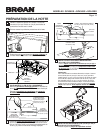
WARNING
To reduce the risk of electrical shock, switch power off
at service panel. Lock or tag service panel to prevent
power from being switched on accidentally.
ELECTRICAL
WIRING BOX
COVER
10 Remove Electrical Wiring Box Cover from inside
of hood and appropriate Electrical Power Cable
Knockout from top or back of hood.
ELECTRICAL
POWER
CABLE
KNOCKOUT
CONNECT THE WIRING
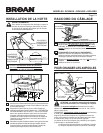
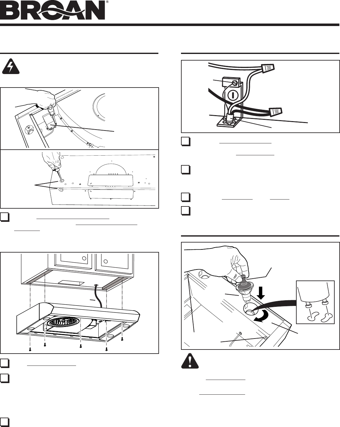
HOW TO CHANGE LIGHT BULBS
Install (4) Halogen Bulbs (included with hood). Use 120 V, 50
W, shielded halogen bulbs - MR16 with GU10 base.
NOTE: Suction Cup Tool (included with hood) can be used to
install and remove light bulbs.
Align pins on bulb with large diameter opening on socket, then
push bulb in towards hood and rotate clockwise until firmly
seated.
The position of the bulb socket (depth) is adjustable and may
require adjustment when:
a) certain brands of bulbs are difficult to install.
b) the bulb protrudes too far below the light panel.
14 Connect House Power Cable to range hood wiring -
BLACK to BLACK, WHITE to WHITE, and GREEN or
BARE WIRE to Ground Screw. Replace electrical wiring
box cover.
HOUSE POWER CABLE
GROUND
SCREW
(1)
PUSH IN
CAUTION: Bulbs may be hot. Refer to bulb
packaging for further information.
(2)
ROTATE
CLOCKWISE
SUCTION
CUP TOOL
HALOGEN
BULB
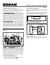
LIGHT PANEL
SCREWS
LIGHT PANEL
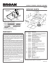
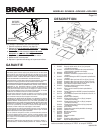
16 Re-attach Bottom Pan with 6 Screws removed in Step 5.
17 Install aluminum filters.
15 FOR 30” MODEL ONLY:
Replace rubber bushing, re-connect left-hand light panel
electrical connector, and re-attach light panel with (2)
screws removed in Step 6.