


Page 4
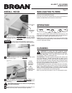
ALLURE™ QS1 SERIES
RANGE HOOD
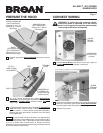
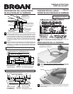
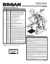
CONNECT WIRING
WARNING: To reduce the risk of electric shock,
make sure power is switched off at the service
panel. Lock or tag service panel to prevent power
from being switched on accidentally.
HOUSE
WIRING
(120 VAC)
CARDBOARD
(Use to protect
cooktop)
1 Connect House Wiring (120 VAC) to hood. Use a piece of
Cardboard to protect the cooktop, if necessary.
2 Connect house black to hood black wire, house white to hood
white wire, and house ground under Green Ground Screw.
Securely tighten cable clamp onto house wiring.
GREEN
GROUND
SCREW
3 Replace wiring cover.
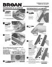
PREPARE THE HOOD
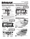
11 Remove appropriate Duct Knockout(s) from top or back of
hood.
REAR
RECTANGULAR
DUCT KNOCKOUT
(Remove for 3¼” x 10”
Horizontal Discharge)
TOP RECTANGULAR
DUCT KNOCKOUT
(Remove for 3¼” x 10”
Vertical & for 7” Round
Discharge)
SEMI-CIRCULAR
DUCT KNOCKOUT
(Remove for 7” Round
Discharge)
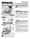
13
7” Round Ducted Discharge Only: Re-install 7” Round Duct
Plate removed in Step #1 under “PREPARE THE HOOD”
section. Install a 7” round damper (purchase separately).
Damper flap must open freely in direction of air flow (away
from range hood).
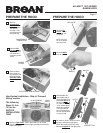
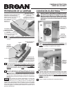
12
3¼” x 10” Ducted Discharge Only: Attach Damper/Duct
Connector over knockout opening. Make sure damper Pivot
is nearest to Top/Back Edge of hood. Remove Tape from
damper flap.
DAMPER/DUCT
CONNECTOR
(Vertical discharge
position shown)
TAPE
UP TO 1”
SIDE-TO-SIDE
ADJUSTMENT
PIVOT
TOP/BACK
EDGE
To accomodate off-center ductwork, the Damper/Duct
Connector can be installed up to 1-inch on either side of
hood center or the 7” Round Duct Plate can be installed
up to ½” on either side of hood center. In extreme off-center
installations, one end of the duct connector may need to be trimmed
to clear the electrical cable clamp.
Ú
NOTE