


3
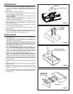
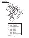
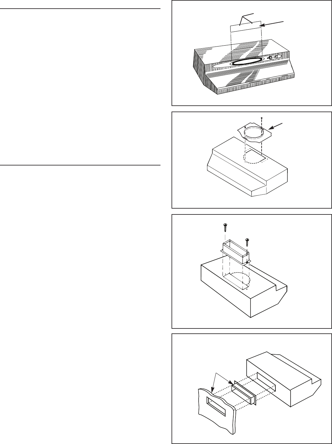
BAFFLE PLATE
LOCATORS
SECURE TRANSITION
WITH SCREWS (Included)
POSITION DUCT
TRANSITION IN
WALL CUTOUT
HORIZONTAL
PREPARATION
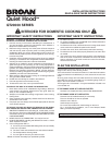
1. Use the dimensional drawings (Refer to FIGURES 1 - 3) to
lay out the range hood’s mounting holes, wiring access and
ductwork by marking the cabinet bottom and drywall where
applicable.
2. Make cutouts for wiring and ductwork.
3. If the hood is to be ducted, install the ductwork so that is flush
to the range hood’s mounting surface.
Refer to FIGURE 1 if the range hood is to be installed with a
horizontal discharge.
Refer to FIGURE 2 and FIGURE 3 if the range hood is to be
installed with a vertical discharge.
4. Run two-conductor wire (with ground) from a power source to
the hood location. Bring approximately 12” of wiring through
wiring hole in cabinet.
5. Drill four 3/32” diameter pilot holes at points where mounting
holes are marked in cabinet bottom.
6. Insert four (4) mounting screws, leaving approximately ¼” of
thread exposed.
7. Remove and retain the mounting screws securing the 3¼” x 10”
and 7” duct transitions to the hood. Install the appropriate duct
transition as described in the installation section.
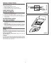
INSTALLATION
1. Remove the necessary duct opening and wiring knockout from
the range hood.
If the range hood is to be installed as a non-ducted unit,
remove the wiring knockout only.
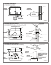
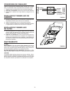
If the range hood is to be installed as a ducted unit, a baffle
plate is provided to close off the non-ducted vent. Install baffle
plate (Refer to FIGURE 4) by sliding into place behind grille.
Use locator bumps to orient in
grille.
2
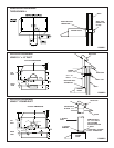
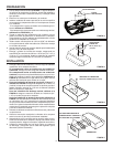
. For 7” round discharge installation, refer to FIGURE 5. Se-
cure 7” adapter (included) to top of hood using screws provided.
Install 7” round damper (Model BP87, purchased separately).
For 3¼” x 10” vertical discharge installation, refer to FIGURE
6. Secure 3¼” x 10” transition (if used) to top of hood.
For 3¼” x 10” horizontal discharge installation, refer to FIG-
URE 7. If using supplied 3¼” x 10” duct transition, secure it to
the range hood. Ensure that the damper flap operates fully and
freely. If it does not, remove the damper flap or make necessary
modifications to the installation to insure full and free operation
of the damper flap.
3. Feed the wiring through the access hold and into the electrical
box.
4. Align hood’s keyhole mounting slots over the four (4) partially
installed screws.
5. Making sure the duct positions over the hood’s duct transition,
push the hood against the rear wall. Secure hood by tightening
screws.
6. Using a long blade screwdriver, reach into the discharge open-
ing and make sure the damper flap operates freely (vertical
discharge only).
FIGURE 4
FIGURE 6
FIGURE 7
7" ROUND
ADAPTER
(Included)
FIGURE 5