7
Physical data (continued)
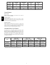
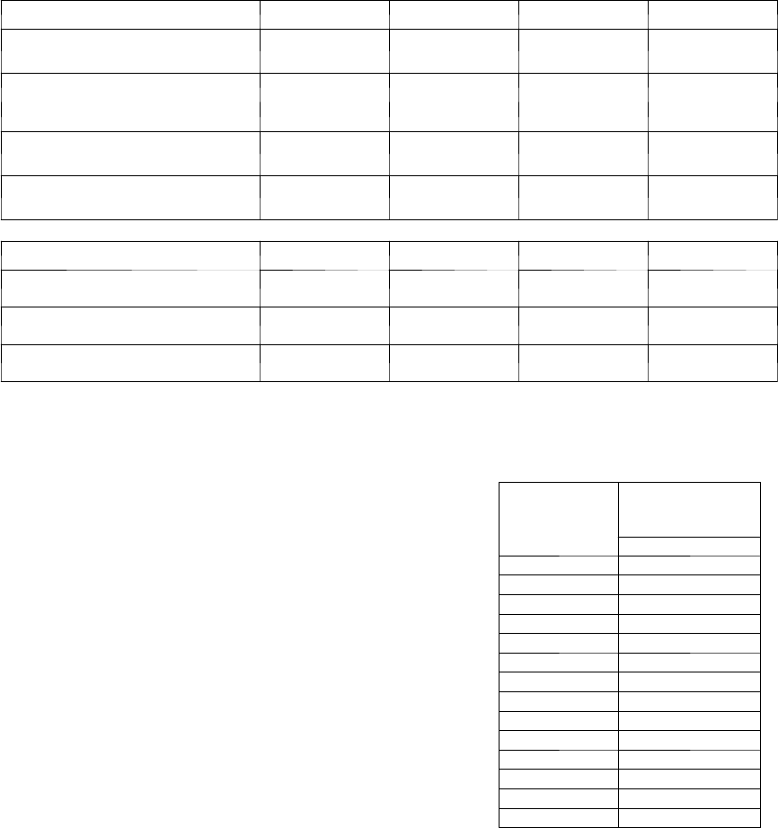
Model
HRVBBLHA1150 HRVBBLHA1250 HRVBBSVA1100 HRVBBSHA1100
Capacity—CFM @
0.5-0.3ESP (in. wc)
130---168 191---210 99---107 99---107
Efficiency (Sensible)—Percent
6
5
6
5
6
6
6
6
E
f
f
i
c
i
e
n
c
y
(
S
e
n
s
i
b
l
e
)
P
e
r
c
e
n
t
32_F(0_ C)
--13_F(--25_ C)
6
5
65
6
5
60
6
6
66
6
6
66
Efficiency (Latent)—Percent
@ all temperatures
0 0 0 0
Heat Core Exchange Area—
cu ft (cu m)
120 (3.4) 166 (4.7) 55 (5.1) 55 (5.1)
Model
HRVBBLHA1150 HRVBBLHA1250 HRVBBSVA1100 HRVBBSHA1100
Voltage 120 120 120 120
MaxPower—watts 150 218 150 150
Max Amps 1.4 1.9 1.3 1.3
Methods to Size HRVs
Method 1:
1. Calculate cubic feet of occupied space
2. Multiply by recommended air changes per hour (AC/h)
3. Divide by 60 minutes per hour to convert to CFM
Example: 2000 sq ft with 8 ft ceiling
0.35 air changes per hour (AC/h)
(2000 sq ft x 8 ft ceiling x 0.35 AC/h) / 60 min/h =
93.3 CFM
Method 2:
1. Multiply number of people tim es 15 CFM/person
2. Multiply number of bathrooms times 20 CFM/each
3.Add25CFMforkitchen
Example: 2 people
2 bathrooms
1 kitchen
(2 x 15) + (2 x 20) + 25 = 95 CFM
Additional heating and cooling load charts
Although the ventilators process the outside air before it enters
the home, additional heating and cooling loads need to be
considered.
HEATING LOAD BTU
Outside Temp
°F
Heat Load (BTUh)
@ Inside Design
Temp 72°F
HRVBBLHA1150
–25 4,688
–20 4,466
–15 4,598
–10 4,334
–5 4,069
0 3,805
5 3,541
10 3,502
15 3,220
20 2,938
25 2,950
30 2,636
35 2,322
40 2,009
The heating load chart shows the heating loads in BTUh for a
range of winter design temperatures for each model of ventilator.
EXAMPLE: The heating design temperature for Milwaukee,
WI, is --4_F. At --5_F, the additional heating load of the
HRVBBLHA1250 is 8417 BTUh. This additional load should be
taken into consideration when sizing the heating equipment.


