Page 4
ELECTRICAL HOOK-UP
CAUTION – Improper electrical installation will damage electronic components.
1. An electrician must provide electrical service as specified.
2. Using a voltmeter, check the voltage and color coding of each conductor at the electrical source.
3. Remove the front panel beneath the sprayhead.
Models with electronic control assemblies:
Place the tank heater switch at the top of the control assembly in the “OFF” position.
Models with electro/mechanical thermostats:
Rotate the control thermostat knob fully counterclockwise to the “OFF” position.
4. Feed the cord through the strain relief and connect it to the terminal block.
5. Connect the brewer to the power source and verify the voltage at the terminal block before proceeding. Re-
place the front panel.
6. If plumbing is to be hooked up later be sure the brewer is disconnected from the power source. If plumbing
has been hooked up, the brewer is ready for Initial Set-Up.
PLUMBING REQUIREMENTS
This brewer must be connected to a cold water system with operating pressure between 20 and 90 psi (138
and 620 kPa) from a
1
⁄
2
" or larger supply line. A shut-off valve should be installed in the line before the brewer.
Install a regulator in the line when pressure is greater than 90 psi (620 kPa) to reduce it to 50 psi (138 kPa).
The water inlet fitting is
1
⁄
4
" flare.
NOTE – Bunn-O-Matic recommends
1
⁄
4
" copper tubing for installations of less than 25 feet and
3
⁄
8
" for more than 25
feet from the
1
⁄
2
" water supply line. A tight coil of copper tubing in the water line will facilitate moving the brewer
to clean the counter top. Bunn-O-Matic does not recommend the use of a saddle valve to install the brewer. The
size and shape of the hole made in the supply line by this type of device may restrict water flow.
27038 050412
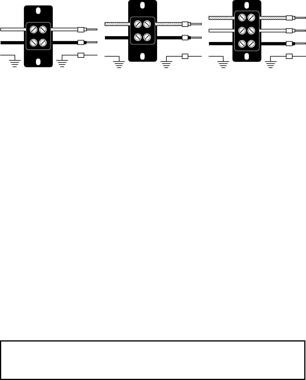
ELECTRICAL REQUIREMENTS
WARNING - The brewer must be disconnected from the power source until specified in Initial Set-Up.
Refer to Data Plate on the Brewer, and local/national electrical codes to determine circuit requirements.
200 and 230 volt ac models
Note: This electrical service consists
of 2 current carrying conductors
(L1 and L2) and a separate conduc-
tor for earth ground.
120/208 & 120/240 volt ac models
Note: This electrical service consists
of 3 current carrying conductors
(Neutral, L1 and L2) and a separate
conductor for earth ground.
L2
L1
G
L2 RED
GREEN GREEN
L1 BLACK
L2 RED
L1 BLACK
L2
N
L1
G
L2 RED
WHITE
GREEN GREEN
NEUTRAL
L1 BLACK
L2 RED
WHITE
NEUTRAL
L1 BLACK
N
L1
G
WHITE
GREEN GREEN
NEUTRAL
L1 BLACK
WHITE
NEUTRAL
L1 BLACK
120 volt ac models
Note: This electrical service consists
of 2 current carrying conductors
(L1 and L2) and a separate conduc-
tor for earth ground.
As directed in the International Plumbing Code of the International Code Council and the Food Code
Manual of the Food and Drug Administration (FDA), this equipment must be installed with adequate
backflow prevention to comply with federal, state and local codes. For models installed outside the
U.S.A., you must comply with the applicable Plumbing /Sanitation Code for your area.


