


4
Electrical Hook-Up
CAUTION – Improper electrical installation will damage electronic components.
1. An electrician must provide electrical service as specified.
2. Using a voltmeter, check the voltage and color coding of each conductor at the electrical source.
3. Connect the dispenser to the power source.
PLUMBING REQUIREMENTS
This dispenser must be connected to a cold water system with operating pressure between 20 and 90 (138
and 620 kPa) psi from a
1
⁄
2
” or larger supply line. A shut-off valve should be installed in the line before the dis-
penser. Install a regulator in the line when pressure is greater than 90 psi (620 kPa) to reduce it to 50 psi (345
kPa). The water inlet fitting is
1
⁄
4
” flare.
NOTE - Bunn-O-Matic recommends
1
⁄
4
” copper tubing for installations of less than 25 feet and
3
⁄
8
” for more than
25 feet from the
1
⁄
2
” water supply line. At least 18 inches of an FDA approved flexible beverage tubing, such as
reinforced braided polyethylene or silicone, before the brewer will facilitate movement to clean the countertop.
Tubing is supplied by Bunn-O-Matic (part number 00326-0000). Bunn-O-Matic does not recommend the use of
a saddle valve to install the brewer. The size and shape of the hole made in the supply line by this type of device
may restrict water flow.
28791 071411
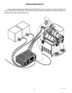
INITIAL SET-UP
NOTE: This refill unit should not be used to initially fill the hopper. Running the motor for extended periods will
trip the thermal switch. The thermal switch will reset, but requires up to 30 minutes of cooling time.
NOTE: Hoses and product container connectors are not supplied. Fitting, clamps and labels are supplied. Make
hose assemblies as required. Refer to PIPING DIAGRAM on page 23.
1. Assemble hoppers with probe housing assemblies to dispenser or modify existing hoppers using template
provided.
2. Make sure probe housing assembly is pushed down into slots on back of hoppers.
3. Install cable assembly to the lower right front of the auto refill box and the probe housing assemblies on the
hoppers. The connectors on the cable pushes in and cap rotates 1/4 turn to lock into position.
4. Run output tubes from auto refill box to the quick disconnects in the hoppers.
NOTE: Make sure numbers on the labels match up. Cable#1 with Hose#1, Cable#2 with Hose#2,....etc.
NOTE - Water pipe connections and fixtures directly connected to a potable water supply shall be sized, installed
and maintained in accordance with federal, state and local codes.
As directed in the International Plumbing Code of the International Code Council and the Food
Code Manual of the Food and Drug Administration (FDA), this equipment must be installed with
adequate backflow prevention to comply with federal, state and local codes. For models installed
outside the U.S.A., you must comply with the applicable Plumbing /Sanitation Code for your area.