10
SERVICE
CIRCUIT BOARD
OFF
OFF
O
N
OFF
OFF
O
N
OFF
OFF
O
N
OFF
OFF
O
N
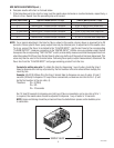
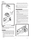
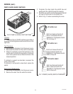
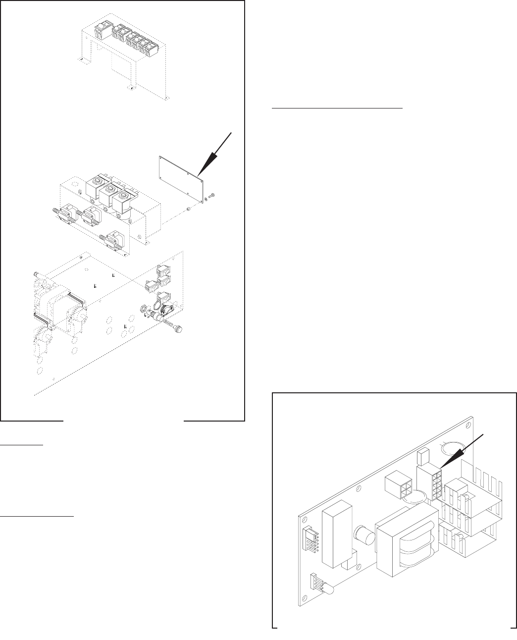
FIG. 2 CIRCUIT BOARD
P1520
Location:
The circuit board is located inside the autofill box,
mounted on the right side of the solenoid mounting
bracket under the switch panel.
Test Procedure:
1. Disconnect the dispenser from the power source.
2. Disconnect the ten pin plug on the main wiring
harness from the connector on the circuit board.
3. Connect the dispenser to the power source. With
a voltmeter, check the voltage across the black
wire(#3) and the white wire (#6). The indication
must be:
a) 120 volts ac for two wire 120 volt models.
b) 200 to 240 volts ac for two wire 200 or 240 volt
models.
J4
J1
J2
J3
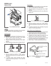
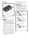
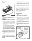
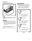
FIG. 3 CIRCUIT BOARD CONNECTOR LOCATION
P1528
28791 040501
c) 230 volts ac for two wire 230 volt models.
4. Disconnect the dispenser from the power source.
If voltage is present as described, replace the circuit
board.
If voltage is not present as described, refer to the
Wiring Diagrams
and check main wiring harness.
Removal and Replacement:
1. Remove the four #8-32 keps nuts securing the
switch mounting bracket. Set aside with the wires
attached.
2. Remove the circuit board shield and set aside for
reassembly.
3. Disconnect the ten pin plug from the main wiring
harness to the circuit board.
4. Remove the six #4-40 screws and spacers secur-
ing the circuit board to the solenoid mounting
bracket. Remove circuit board and discard.
5. Install new circuit board using #4-40 screws and
spacers to secure the circuit board to the solenoid
mounting bracket. The spacers must be between
the solenoid mounting bracket and the circuit
board.
6. Place circuit board shield over the circuit board.
7. Install switch panel assembly and secure with four
#8-32 keps nuts.
8. Refer to Fig. 3 for circuit board ten pin connector.


