


12
SERVICE
This section provides procedures for testing and
replacing various major components used in this dis-
penser should service become necessary. Refer to
Troubleshooting
for assistance in determining the cause
of any problem.
WARNING - Inspection, testing, and repair of electrical
equipment should be performed only by qualified ser-
vice personnel. The dispenser should be unplugged
when servicing, except when electrical tests are re-
quired and the test procedure specifically states to
plug-in the dispenser.
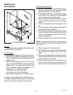
COMPONENT ACCESS
WARNING - Disconnect the dispenser from the power
source before the removal of any panel or the replace-
ment of any component.
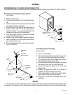
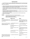
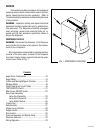
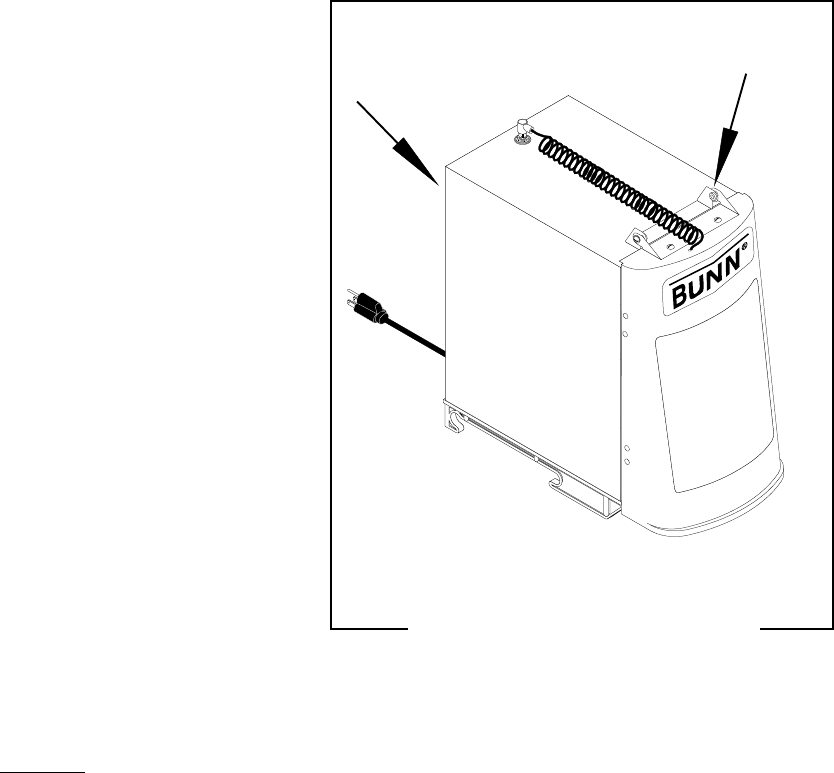
All components are accessible by opening the door,
removal of the door panel, removal of the dispenser
rear panel, hopper, hopper support plate and top wrap-
around cover. Refer to Fig. 1
Contents
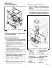
Auger Drive Components......................................13
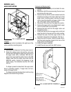
Auger Motor .........................................................14
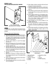
Frother and Mixing/Whipper Chamber..................15
Whipper Motor .....................................................16
Control Board and Level Probes ...........................18
TEST/SERVICE Switch ..........................................21
Main Power ON/OFF Switch..................................22
Door Panel Assembly
Lamp Cord Assembly .....................................23
Lamp Cord Connector.....................................24
Lamp Holder/Socket .......................................25
Transformer ..........................................................26
Potentiometer .......................................................27
Hopper Level Indicator .........................................28
Hopper Switch ......................................................29
Door Switch..........................................................30
Pressure Regulator and Needle Valve ...................31
Dispense Solenoid ................................................32
Wiring Diagrams...................................................33
P1891
FIG. 1 COMPONENT LOCATIONS
29793 061599