Page 28
29707 012502
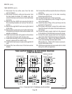
11. Disconnect the two white wires from the tank
warmer blanket.
12. Disconnect the black, white and blue wires from
the tank heater terminals. DV models only, dis-
connect the brown and red wires from tank heater
terminals.
13. Remove the four #8-32 nuts securing the tank to
the mounting brackets and remove the tank as-
sembly.
14. Remove the eight #8-32 nuts securing the tank lid
to the tank.
15. Remove the two hex nuts securing the tank heater
to the bottom of the tank. Remove tank heater with
gaskets and discard.
16. Install new tank heater with gaskets to the bottom
of the tank and secure with two hex nuts.
17. Install tank assembly onto mounting brackets and
secure in place with four #8-32 nuts.
18. Install tank lid and secure in place with eight #8-32
nuts.
19. Connect the two white wires of the tank warmer
blanket.
SERVICE (cont.)
TANK HEATERS (cont.)
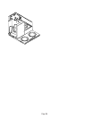
P1888
TANK HEATER TERMINAL BLOCK WIRING DIAGRAM
(CDBC-MV MODELS)
REDWHIBLK
REDWHIBLK BLK WHIRED
120V A.C.
120V A.C.
208 or
240V A.C.
WHITE
NEUTRAL
L1 BLACK
L2 REDL2 REDL2 RED
1800W @ 120V
1425W @ 120V
2390W @ 120/208V
or
3180W @ 120/240V
120V A.C.
WHITE
NEUTRAL
L1 BLACK
120V A.C.
WHITE
NEUTRAL
L1 BLACK
1800W
1425W
B
L
K
B
L
U
W
H
T
1800W
1425W
B
L
K
B
L
U
W
H
T
1800W
1425W
B
L
K
B
L
U
W
H
T
FIG. 9 TANK HEATER TO TERMINAL BLOCK WIRING
20. Connect the limit thermostat to the front of the tank
assembly.
21. Connect the green wire to the tank mounting
bracket using #8-32 nut.
22. Connect the pink wire to the level probe.
23. Insert the temperature probe through the grom-
met in the tank lid.
24. Install the elbow fitting of the vent hose into the
grommet in the tank lid.
25. On brewers with faucet, connect the outlet water
line of the faucet to the side of the tank and secure
with clamp.
26. Connect the water supply tube from the solenoid
to the bottom of the tank and secure with clamp.
27. Connect the water supply tube from the dispense
valve to the side of the tank and secure with clamp.
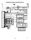
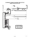
28. DV models only - Refer to the
Wiring Diagrams
when reconnecting the tank heater wires.
MV models only - Refer to FIG. 9 when reconnect-
ing the tank heater wires.
29. Install access panels and covers and refer to
Initial
Set-up
for refill and operation.


