


Page 20
BUNN
M
A
N
U
F
A
C
T
U
R
E
D
B
Y
B
U
N
N
-
O
-
M
A
T
IC
C
O
R
P
O
R
A
T
IO
N
S
P
R
I
N
G
F
I
E
L
D
,
I
L
L
I
N
O
I
S
,
U
.
S
.
A
.
M
O
D
E
L
S
/
N
V
O
L
T
S
A
.
C
.
A
M
P
W
A
T
T
S
P
H
A
S
E
W
I
R
E
H
E
R
T
Z
C
O
V
E
R
E
D
U
N
D
E
R
O
N
E
O
R
M
O
R
E
O
F
T
H
E
F
O
L
L
O
W
I
N
G
P
A
T
E
N
T
S
:
O
N
E
O
R
M
O
R
E
O
T
H
E
R
P
A
T
E
N
T
S
M
A
Y
B
E
P
E
N
D
I
N
G
DISCONNECT FROM POWE
R SOU
RCE
BEFORE REMOVAL OF AN
Y PANEL OR
REPLACEMEN
T OF ANY COM
PONEN
T!
W
A
R
N
I
N
G
!
C
A
U
T
IO
N
:
W
A
R
M
E
R
S
A
N
D
S
U
R
F
A
C
E
S
A
R
E
H
O
T
BUNN
M
A
N
U
F
A
C
T
U
R
E
D
B
Y
B
U
N
N
-
O
-
M
A
T
I
C
C
O
R
P
O
R
A
T
IO
N
S
P
R
I
N
G
F
I
E
L
D
,
I
L
L
I
N
O
I
S
,
U
.
S
.
A
.
M
O
D
E
L
S
/
N
V
O
L
T
S
A
.
C
.
A
M
P
W
A
T
T
S
P
H
A
S
E
W
I
R
E
H
E
R
T
Z
C
O
V
E
R
E
D
U
N
D
E
R
O
N
E
O
R
M
O
R
E
O
F
T
H
E
F
O
L
L
O
W
I
N
G
P
A
T
E
N
T
S
:
O
N
E
O
R
M
O
R
E
O
T
H
E
R
P
A
T
E
N
T
S
M
A
Y
B
E
P
E
N
D
I
N
G
SERVICE
This section provides procedures for testing and
replacing various major components used in this
brewer should service become necessary. Refer to
Troubleshooting
for assistance in determining the
cause of any problem.
WARNING - Inspection, testing, and repair of electri-
cal equipment should be performed only by qualified
service personnel. The brewer should be unplugged
when servicing, except when electrical tests are re-
quired and the test procedure specifically states to
plug-in the brewer.
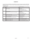
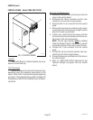
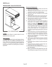
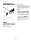
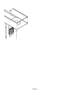
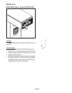
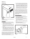
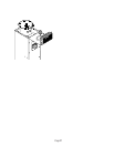
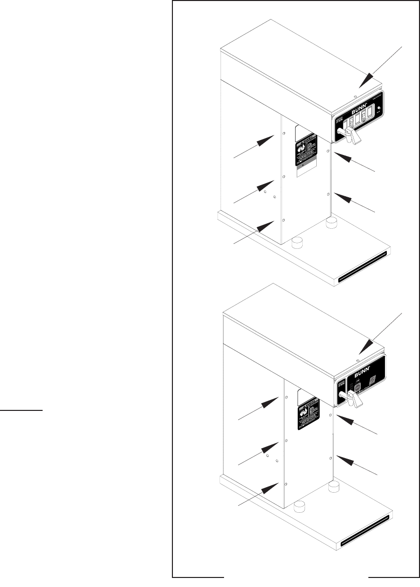
COMPONENT ACCESS
WARNING - Disconnect the brewer from the power
source before the removal of any panel or the replace-
ment of any component.
All components are accessible by the removal of
the top cover or warmer housing and front access
panel.
The top cover is attached with one #4-40 screw.
The front access panel is attached with four #6-32
screws.
P1913
Contents
Control Board - CDBC-APS/TS/TSR ...................21
Control Board - CEZ-APS/TS/TSR......................22
Switch Panel - CDBC-APS/TS/TSR ...................23
ON/OFF Switch - CEZ-APS/TS/TSR ....................24
BREW Switch (Start) - CEZ-APS/TS/TSR...........25
Dispense Valve ..................................................26
Limit Thermostat ............................................... 27
Tank Heater ....................................................... 28
Refill Valve .........................................................30
Wiring Diagrams............................................... 31
FIG. 1 COMPONENT ACCESS
29253 030101