


Page 15
SERVICE (cont.)
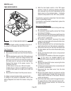
Test Procedures:
1. Disconnect the brewer from the power source.
2. Locate the blue wire on the control thermostat.
3. Check the voltage across the blue wire on the
control thermostat and the white insert on two
pole 120 volt terminal block or three pole 120/240
volt terminal blocks and the red insert on two wire
200 volt or 240 volt terminal block with a voltme-
ter. Connect the brewer to the power source. The
indication must be:
a) 120 volts ac for two wire 120 volt models and
three wire 120/240 volt models.
b) 200 to 240 volts ac for two wire 200 or 240 volt
models.
4. Disconnect the brewer from the power source.
If voltage is present as described, proceed to #5.
If voltage is not present as described, refer to the
wiring diagrams and check the brewer wiring harness.
5. Locate the black wire on the control thermostat.
6. Gently remove the capillary bulb and grommet
from the tank.
7. Check the voltage across the black wire of the
control thermostat and the white insert on the two
pole 120 volt or three pole 120/240 volt terminal
block and the red insert on the two pole 200 volt or
240 volt terminal block with a voltmeter when the
control thermostat is turned fully clockwise. Con-
nect the brewer to the power source. The indica-
tion must be:
a) 120 volts ac for two wire 120 volt models and
three wire 120/240 volt models.
b) 200 to 240 volts ac for two wire 200 volt or 240
volt models.
8. Disconnect the brewer from the power source.
If voltage is present as described, reinstall the capillary
tube into the tank to the line 4.5" above the bulb, the
control thermostat is operating properly.
If voltage is not present as described, replace the
thermostat.
CONTROL THERMOSTAT (cont.)
10478 061500
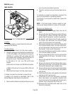
Removal and Replacement:
1. Disconnect the control thermostat wires.
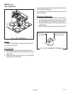
2. Remove the thermostat capillary bulb by firmly
pulling-up on the capillary at the tank lid. This will
disengage the grommet from the tank lid.
3. Remove the one #8-32 screw securing the control
thermostat to the component bracket inside the
trunk.
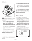
4. Slide the grommet to the line 4.5" above the bulb
on the new capillary tube.
5. Insert the capillary bulb through the hole in the
tank lid and press the grommet firmly and evenly
so that the groove in the grommet fits into the tank
lid.
6. Carefully bend the capillary tube so that the tube
and bulb inside the tank are in the vertical position.
NOTE - The capillary tube must be clear of any electri-
cal termination and not kinked.
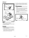
7. Using one #8-32 screw, secure the control ther-
mostat to the component bracket inside the trunk.
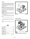
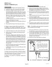
8. For first type thermostat, refer to the Fig. 3 when
reconnecting thermostat wires. For second type
thermostat, it does not matter which lead is con-
nected to which terminal.
9. Adjust the control thermostat as required.
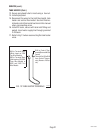
P1129
FIG. 3 CONTROL THERMOSTAT TERMINALS
First Type Thermostat
Second Type Thermostat
BLU to BLU wire from Limit
Thermostat
BLK to BLK Wire from Tank
Heater (Brewers w/out Faucet)
BLK to Thermal Cut-Off from
Tank Heater (Brewers with Fau-
cet)