


El ECT RI C IAN'S INS TAL lA T ION INS T RUCT ION S
MODEL f·35
MODELS f·15
& f·20
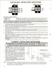
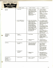
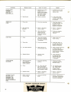
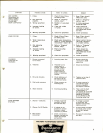
ELECTRICAL REQUIREMENTS:
1
• MODELS F35 120/240 volts A.C., 60 hertz, 3 wire, single phase. 20 amp. wiring required.
• MODEL F20 120 volts A.C., 60 hertz, 2 wire, single phase. 20 amp. wiring required.
• MODEL F15 120 volts A.C., 60 hertz, single phase, with two wire grounded cord. 15 amp.
WARNING: CHASSIS MUST BE PROPEBL Y GROUNDED TO PREVENT POSSIBLE SHOCK HAZARD. ON CORD CONNECTED MODELS
THAT HAVE A GROUNDING LEAD PROVIDED, IF AN ADAPTIVE PLUG MUST BE USED, AN ELECTRICAL GROUND MUST BE PRO-
VIDED. DO NOT ASSUME A PLUMBING LINE WILL PROVIDE SUCH A GROUND.
1. Electrician must provide the outlet, plug to match, and a suitable length of cord or armored cable if
not supplied. (Attached power supply cord provided on Model F15).
2. Power is to be left OFF throughout installation.
3. Before connecting electrically, remove front panel via two screws and be sure the thermostat is
turned all the way to the left (counterclockwise) to the OFF position. Keep in the OFF position until
tank has been filled with water.
4. Electrical service is connected to the termina"1"block at the front of the brewer. Remove front panal via
two screws for access. Strain relief is provided in the rear of the machine.
5. No switch is required. All models should remain connected electrically so heat will be maintained in
the water tank.
6. After connecting service as specified, test the voltage on the field wired side with a voltmeter. Should
be as shown above.
7. With power to brewer OFF, replace front panel. If plumbing connection has been made, the coffee '.......,)
brewer is now ready for "Initial Operation Instructions." Refer to page 3. If plumbing is to be done
later, be sure that power is OFF.
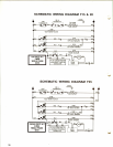
NOTE: Schematic and pictorial wiring diagrams are located on page 10 of manual.
WARNING: Brewer warranty is void if brewer is connected to any voltage other than specified on
nameplate ..
In all installations, the National and-all local electrical codes must be followed.
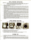
PLUMBER'S INSTAllATION INSTRUCTIONS
The equipment is to be installed to comply with the Basic Plumbing Code of the
Building Officials and Code Administrators International, Inc. (BOCA) and the
Food Service Sanitation Manual of the Food and Drug Administration (FDA).
CAUTION: Power to brewer must be OFF
before proceeding with plumbing installation.
1. Flush water line before installing brewer.
Brewer should be connected on Cold Water
Line for best operation.
2. Water pressure should be at least 20 Ibs. For
less than a 25 ft. run, use 1/4" copper tubing
from
1/2" or larger water line_ For more than a
25 ft. run, use 3/8" copper tubing from 1/2" or
larger water line, and provide an adapter fit-
ting for conne.ction to the water strainer.
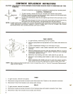
3. Connect incoming water line to the incoming
male fitting on the strainer.
A SHUT OFF VALVE SHOULD BE INSTALLED
ON THE INCOMING WATER LINE IN A CON-
VENIENT LOCATION.
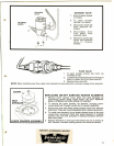
i ;
I: 1
18" COPPER TUBING-LEADS TO
SOLENOID MALE FLARE
FITTING (SUPPLIED BY BOM)
1/4" FEMALE SAE. FLARE FITTING
/ / (SUPPLIED BY BOM)
/~ WATER STRAINER (SUPPLIED BY BOM)
U .."..··.-; "'~''- -' . ,/- 1/4" FEMALE SAE. FLARE FITTING
='::':':''-' " // (SUPPLIED BY PLUMBER)
== ", :""'. /. --,-, COPPER TUBING
~ .J·t:, ~~UPPLIED BY PLUMBER)
SHuro~ , J(SUPPLIED BY PLUMBER) ~
NOTE: The National Sanitation Foundation requests a provision be made in the incoming water line
for flexibility. This is necessary to allow tilting or moving the brewer for proper cleaning
underneath, etc. A tightly coiled length of copper tubing located ahead of the water strainer
would help comply with this request.
2