


22
J4
J1
J2
J3
J4
J1
J2
J3
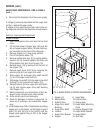
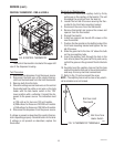
Tank Heater Relay Control Circuitry (Control Board
#2)(120V dispensers only):
1. Disconnect the dispenser from the power source.
2. Disconnect the six pin connector from J3 of con-
trol board #2.
3. Check the voltage across pins 5 & 6 of the six pin
connector on the wiring harness with a voltmeter.
Connect the dispenser to the power source. the
indication must be 24 volts ac.
4. disconnect the dispenser from the power source.
If voltage is present as described, proceed to step 5.
If voltage is not present as described, refer to the
wiring diagram and check the dispenser wiring har-
ness.
5. Reconnect the six-pin connector of the wiring
harness to J3 of control board #2.
6. Disconnect the four-pin connector from J4 of
control board #2.
7. Check the voltage across pins 1 & 4 of the four-pin
connector on the wiring harness with a voltmeter.
The indication must be 120 volts ac.
8. Disconnect the dispenser from the power source.
If voltage is present as described, proceed to step 9.
If voltage is not present as described, refer to the
wiring diagram and check the dispenser wiring har-
ness.
9. Reconnect the four-pin connector of the wiring
harness to J4 of control board #2.
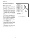
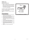
10. Check the voltage across the coil terminals of the
tank heater relay with a voltmeter. Connect the
dispenser to the power source. The indication
must be 0 volts ac.
If voltage is absent as described, proceed to step 11.
If voltage is present, replace the control circuit board
#2.
11. Place containers below any three dispenser nozzles.
12. Simultaneously initiate dispenses at each of the
selected dispense stations while monitoring the
voltage across the coil terminals of the tank heater
relay. The indication must be 120V ac.
If voltage is present as described, the control board #2
is functioning correctly.
If voltage is not present as described, replace the
control circuit board #2.
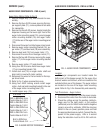
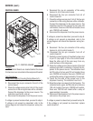
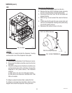
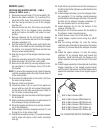
Removal and Replacement:
1. Disconnect the three plugs on the main wiring
harness from the connectors on the control board.
2. Remove the four #6-32 keps nuts securing the
control board to the component bracket.
3. Remove control board and discard.
4. Install new control board on the component bracket
using four #6-32 keps nuts.
5. Reconnect the three plugs on the main harness to
the connectors on the control board.
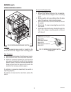
NOTE: J4 is not connected on Control Board #2 on
120/208 - 240V dispensers.
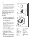
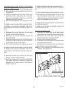
J4 J3
FIG. 12 CONTROL BOARD CONNECTORS
P2637
J1 J2
J1 J2
J4 J3
CONTROL BOARD #1
CONTROL BOARD #2
35135 111103