


Operating The Tool
(Continued)
3. After adding oil, run
tool briefly. Wipe off
any excess oil from
the cap exhaust.
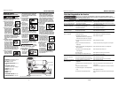
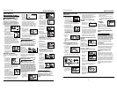
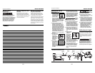
RECOMMENDED HOOKUP
The illustration below shows the
recommended hookup for the tool.
1. The air com-
pressor must
be able to
maintain a
minimum of
60 psi when
the tool is being used. An inade-
quate air supply can cause a loss of
power and inconsistent driving.
2. An oiler can be used
to provide oil circula-
tion through the tool.
A filter can be used
to remove liquid and
solid impurities which
can rust or “gum up” internal parts
of the tool.
3. Use 3/8” air
hoses with a
minimum
working pres-
sure of 150
psi. Use 1/2” air hoses for 50’ run or
longer. For better performance,
install a 3/8” quick plug (1/4” NPT
threads) with an inside diameter of
.315" (8mm) on the tool and a 3/8”
quick coupler on the air hose.
4. Use a pressure
regulator on the
compressor, with
an operating
pressure of 0 -125
psi. A pressure regulator is required
to control the operating pressure of
the tool between 60 and 100 psi.
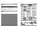
SINGLE SEQUENTIAL MODE
This mode
requires the trig-
ger to be pulled
each time a fas-
tener is driven. The tool can be actuat-
ed by depressing the WCE against the
Cómo usar la
Herramienta (Cont.)
COMO CHEQUEAR EL ELEMENTO DE
CONTACTO
Chequée
el fun-
cionamiento del mecanismo del ele-
mento de contacto antes de cada uso.
El elemento de contacto se debe
desplazar libremente, sin pegarse, a lo
largo del área de desplazamiento. El
resorte del elemento de contacto debe
regresar el elemento de contacto a su
posición original totalmente extendido.
No use la herramienta si el mecanismo
del elemento de contacto no está fun-
cionando adecudamente. Podría oca-
sionarle heridas.
1.
Desconecte la
herramienta de
la fuente de su-
ministro de
aire.
2. Saque todos
los sujetadores
del cargador
(Vea la Sección
Carga-
Descarga)
3. Cerciórese de que
el gatillo y el ele-
mento de contacto
se muevan libre-
mente en ambos
sentidos sin atascarse o pegarse.
4. Reconecte la
herramienta a la
fuente de sumi-
nistro de aire.
5.
Presione el
Elemento de
Contacto de Trabajo
contra la superficie
de trabajo sin apre-
tar el gatillo. La herramienta NO
DEBE OPERAR. No use la herra-
mienta si opera sin apretar el gatillo.
Se pueden producir lesiones person-
ales.
6. Remueva la her-
ramienta de la super-
ficie de trabajo. El
Elemento de
Contacto de Trabajo
tiene que volver a su posición origi-
nal. La herramienta NO DEBE
OPERAR. No use la herramienta si
opera mientras está levantada de la
superficie de trabajo.
7. Apriete el
gatillo y pre-
sione el
Elemento de
Contacto de Trabajo contra la super-
ficie de trabajo. La herramienta
DEBE OPERAR.
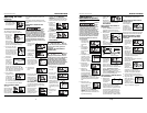
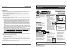
PARA CARGAR Y DESCARGAR LA
HERRAMIENTA
1. Siempre conecte la herramienta a
la fuente de suminsitro de aire
antes de colocarle los sujetadores.
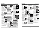
2. Empuje hacia
abajo sobre el
boton del
seguro. Mueva
la tapa del
cargador hacia
atrás.
3. Para grapas, cargue una tira de gra-
pas con las coronas montadas sobre
el riel del cargador.
4. Empuje la tapa
del cargador
hacia delante
hasta que el
botón del
seguro salte hacia arriba.
5. Siempre descargue el sujetador
antes de remover la herramienta de
servicio. La descarga se hace
siguiendo el proceso inverso de la
carga; sin embargo, siempre se
tiene que desconectar la manguera
de aire antes de descargarla.
PARA AJUSTAR LA PENETRACION DE
LOS SUJETADORES
1. Regule la pre-
sión de aire en
la herramienta
a 3,45 bar.
2. Conecte las mangueras de aire y
pruebe la penetración clavando
unos sujetadores en un pedazo de
madera. Si éstos no penetran hasta
el nivel deseado, aumente la pre-
sión de aire y pruebe una vez más,
continúe haciéndolo hasta lograr
los resultados deseados. La presión
de la herramienta no debe exceder
6,90 bar ya que ésto reduciría la
durabilidad de la herramienta.
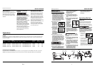
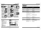
PARA AJUSTAR LA DIRECCION DEL
TUBO DE ESCAPE
La herramienta
está equipado con
un deflector
ajustable de la
dirección del tubo
de escape. Éste le
permite al usuario cambiar la dirección
del tubo de escape. Simplemente mueva
el deflector hacia la dirección deseada.
QUÉ HACER CUANDO LA HERRA-
MIENTA TENGA UN SUJETADOR
ATASCADO
1.
Desconecte la
herramienta de
la fuente de
suministro de
aire.
2. Remueva
todos los suje-
tadores del
depósito (vea
Para Cargar
/Descargar la Herramienta). De lo
contrario, hará que los sujetadores
se expulsen desde la parte
delantera de la
herramienta cuando se remueve el
conjunto de la boca.
3. Remueva (3)
tornillos de
cabeza de la
boca de la her-
ramienta.
Remueva la placa de la boca, el
espaciador y el Elemento de
Contacto de Trabajo para dejar
expuesto el sujetador atascado.
4.
Vuelva a instalar el conjunto de la
boca en el orden inverso del paso Nº3.
5. Asegúrese que el
gatillo funciona y
que el Elemento de
Contacto de
Trabajo se mueve
libremente hacia arriba y hacia
abajo sin atascarse o pegarse.
Modelo SN318K00
21 Sp
Manual de Instrucciones
position. The tool MUST NOT
OPERATE. Do not use the tool if it
operates while lifted from the work
surface. Personal injury may result.
7. Pull the trig-
ger and
depress the
work contact
element
(WCE) against the work surface. The
tool MUST NOT OPERATE.
8. Depress the
Work Contact
Element
(WCE) against
the work sur-
face. Pull the trigger. The tool
MUST OPERATE.
An
improperly functioning tool must not
be used. Do not actuate the tool unless
the tool is placed firmly against the
work piece.
CHECKING THE WORK CONTACT
ELEMENT (WCE)
Check the
operation of the Work Contact Element
(WCE) trip mechanism before each use.
The WCE must move freely without bind-
ing through its entire travel distance.
The WCE spring must return the WCE to
its fully extended position after being
depressed. Do not operate the tool if the
WCE trip mechanism is not operating
properly. Personal injury may occur.
1. Disconnect the
air supply from
the tool.
2. Remove all fas-
teners from
the magazine.
(See "Loading/
Unloading the Tool" section.)
3. Make sure the trigger and Work
Contact Element
(WCE) move freely
up and down with-
out sticking or bind-
ing.
4. Reconnect air
supply to the
tool.
work surface followed by pulling the
trigger.
The trigger must be released to reset
the tool before another fastener can be
driven.
OPERATING A SEQUENTIAL TRIP
NAILER
Check
the operation of the Work Contact
Element (WCE) trip mechanism before
each use. The WCE must move freely
without binding through its entire trav-
el distance. The WCE spring must return
the WCE to its fully extended position
after being depressed. Do not operate
the tool if the WCE trip mechanism is
not operating properly. Personal injury
may occur.
1. Disconnect the
air supply from
the tool.
2. Remove all fas-
teners from the
magazine (see
Loading/
Unloading).
3. Make sure the trig-
ger and work con-
tact element (WCE)
move freely up and
down without stick-
ing or binding.
4. Reconnect air
supply to the
tool.
5. Depress the Work
Contact Element
(WCE) against the
work surface with-
out pulling the trig-
ger. The tool MUST
NOT OPERATE. Do not use the tool
if it operates without pulling the
trigger. Personal injury may result.
6. Remove the tool
from the work sur-
face. The Work
Contact Element
(WCE) must return to
its original down
Model SN318K00
Operating Instructions
4
www.chpower.com
150 PSI WP
3/8” I.D.
60 psi
Min.
100 psi
Max.
Carril del cargador
movemiento
movement
Rotate
Gire
BUILT TO LAST
BUILT TO LAST
BUILT TO LAST
BUILT TO LAST
movement
BUILT TO LAST
BUILT TO LAST
BUILT TO LAST
BUILT TO LAST
BUILT TO LAST
1
2
BUILT TO LAST
BUILT TO LAST
1
2
Botón del
seguro
movemiento