


32
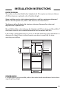
UNPACKING THE COOKER
Unpack the components from inside the grill and oven: Check that the following parts
are present.
Grill pan and grid Top oven/grill shelf heat shield
Baking dish Pan supports (4)
Enamelled burner caps (4) Main oven shelves (2)
Top oven/grill shelf (1) Literature
Aluminium burner bodies (4)
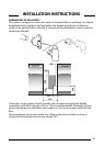
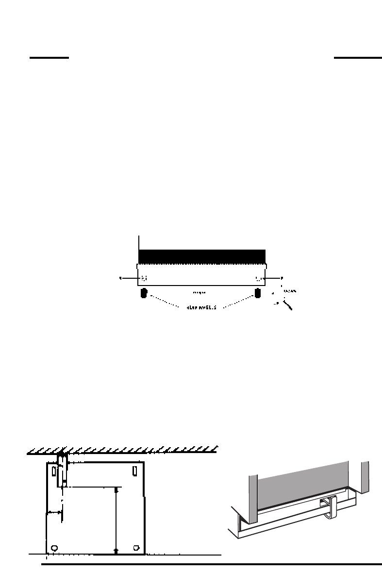
LEVELLING
Two rear wheels and two front feet are fitted which can be adjusted up or down to set
the height (900mm - 915mm) and level the cooker.
1. The rear wheels can be raised or lowered from the BACK of the cooker by
adjusting the levelling screws ‘A’ in the plinth.
2. The front feet can be simply screwed in or out to lower or raise the front of the
cooker.
CAUTION: Some soft floor coverings may get damaged if the cooker is not moved
carefully.
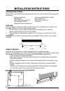
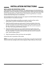
STABILITY BRACKET
The back of the cooker has a slot for engagement of a stability bracket,
which can be obtained, as an extra, from the cooker supplier. The leaflet included with
the bracket should be read in conjunction with the following instructions;
Push cooker to its intended position.
Draw pencil lines on the floor in line with the front and left side of the plinth.
Remove the cooker.
Position stability bracket in accordance with diagram below and secure to the
floor.
Measure height from floor level to the bottom of the slot in the back of the
cooker.
Add 3mm to the dimension and assemble the stability bracket to that height.
(i.e. from floor level to the underside of the top member).
PENCIL LINE
‘B’
410mm
‘A’
92
mm
INSTALLATION INSTRUCTIONS