


SECTION 6
6-23 T-268-07
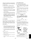
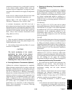
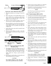
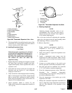
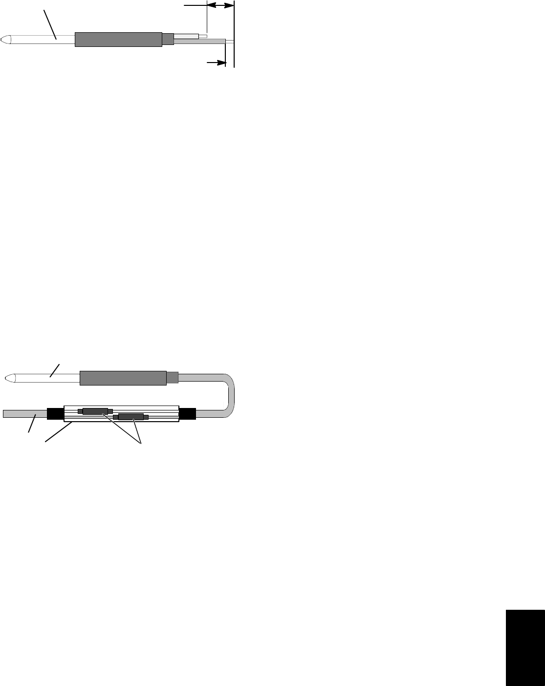
Sensor
41 mm (1-5/8 inches)
6.35 mm (1/4 inch)
Figure 6-22. Sensor (RRS, RTS, SRS or STS)
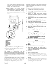
f. Strip back insulation on all wiring 6.35 mm (1/4
inch).
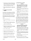
g. Slide a large piece of heat shrink tubing over the
cable, and place the two small pieces of heat shrink
tubing, one over each wire, before adding crimp
fittings as shown in F igure 6-23.
h. Slide the cap and grommet assembly, which was
saved in step (c.), onto the replacement sensor.
i. Slip crimp fittings over dressedwires (keepingwire
colors together). Make sure wires are pushed into
crimp fittings as far as possible and crimp with
crimping tool.
j. Solder spliced wires with a 60% tin and 40% lead
Rosincore solder.
k. Slide heat shrink tubing over splice so that both
ends oftubing coverboth ends ofcrimp as shownin
Figure 6-23.
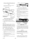
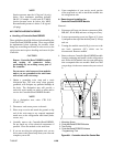
Sensor
Cable
Heat Shrink
Tubing (2)
Large Heat Shrink
Tubing (1)
Figure 6-23. Sensor and Cable Assembly (RRS,
RTS, SRS or STS)
l. Heat tubing,preferably withaflamelessheat gun.If
not available, a propane torch will work (caution
shouldbe takennot toburnt he heat shrinktubingor
wire insulation). Make sure all seams are sealed
tightly against the wiring to prevent m oisture
seepage.
m. Slide large heat shrink tubing over both splices and
shrink tubing and heat as in step (l.).
CAUTION
Do not allow moisture to enter wire splice
area as this may affect the sensor resistance.
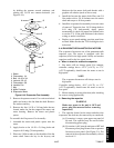
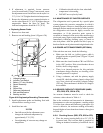
n. Position sensor in unit per Figure 6-21 and check
sensor resistance as detailed in section 6.23. 1.
o. Reinstall the cover (if present) that was removed in
step (b.) over wiring and probe holder.
NOTE
The P5 Pre-Trip test must be run to inactivate
the alarm (refer to section 3.2.1).
6.23.3 R eplacing Sensor (RRS and RTS)
a. Turn unitpower OFF and disconnect powersupply.
b. Cutcable5 cm (6 inches)fromshoulderofdefective
sensor and discard the defective probe only.
c. Cut onewireof existingcable41 mm(1-5/8inches)
shorter than the other wire.
d. Cut one replacement sensor wire (opposite color)
back 41 mm (1-5/8 inches). (See Figure 6-22.)
e. Strip back insulation on all wires 6.35 mm (1/4
inch).
f. Slide a large piece of heat shrink tubing over the
unit cable, a nd place the two small pieces of heat
shrink tubing, one over each wire, before adding
crimp fittings as shown in Figure 6-23.
g. Slip crimp fittings over dressedwires (keepingwire
colors together). Make sure wires are pushed into
crimp fittings as far as possible and crimp with
crimping tool.
h. Solder spliced wires with a 60% tin and 40% lead
Rosincore solder.
i. Slide heat shrink tubing over splice so that both
ends oftubing coverboth ends ofcrimp as shownin
Figure 6-23.
j. Heat tubing,preferably withaflamelessheat gun.If
not available, a propane torch will work (caution
shouldbe takennot toburnt he heat shrinktubingor
wire insulation). Make sure all seams are sealed
tightly against the wiring to prevent m oisture
seepage.
k. Slide large heat shrink tubing over both splices and
shrink tubing and heat as in step (j).
CAUTION
Do not allow moisture to enter wire splice
area as this may affect the sensor resistance.
l. Check sensor resistance as detailed in section
6.23.1.
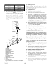
m. Reinstall the return sensor as shown in Figure 6-24.
Forproper placement of thereturn sensor, b e s ureto